GM Service Manual Online
For 1990-2009 cars only

The LPG system works with the petrol system to make a dual fuel vehicle. The LPG system comprises of an LPG tank located in the boot, an LPG filler located in the petrol filler compartment, two LPG lock-off's one is located on the LPG tank and the other underneath the driver, an LPG convertor located behind the left front wheelhouse liner, an LPG control module located behind the right front wheelhouse liner, six LPG injectors located on top of the engine, an LPG switch/gauge located in the floor console in the cigarette lighter compartment, LPG diagnostic connector and fuses located on the left of the radiator.

The fuel selector switch has two positions and a fuel indicator lamp, which changes colour to indicate which fuel mode the vehicle is currently on. Red indicates petrol, amber indicates currently transferring to selected fuel and green is LPG operation. When LPG is selected the engine will start and run on petrol until the required conditions are reached, at which time the system will automatically transfer to LPG operation. When operating on LPG, during certain higher RPM and load conditions, the system will electronically switch to petrol.
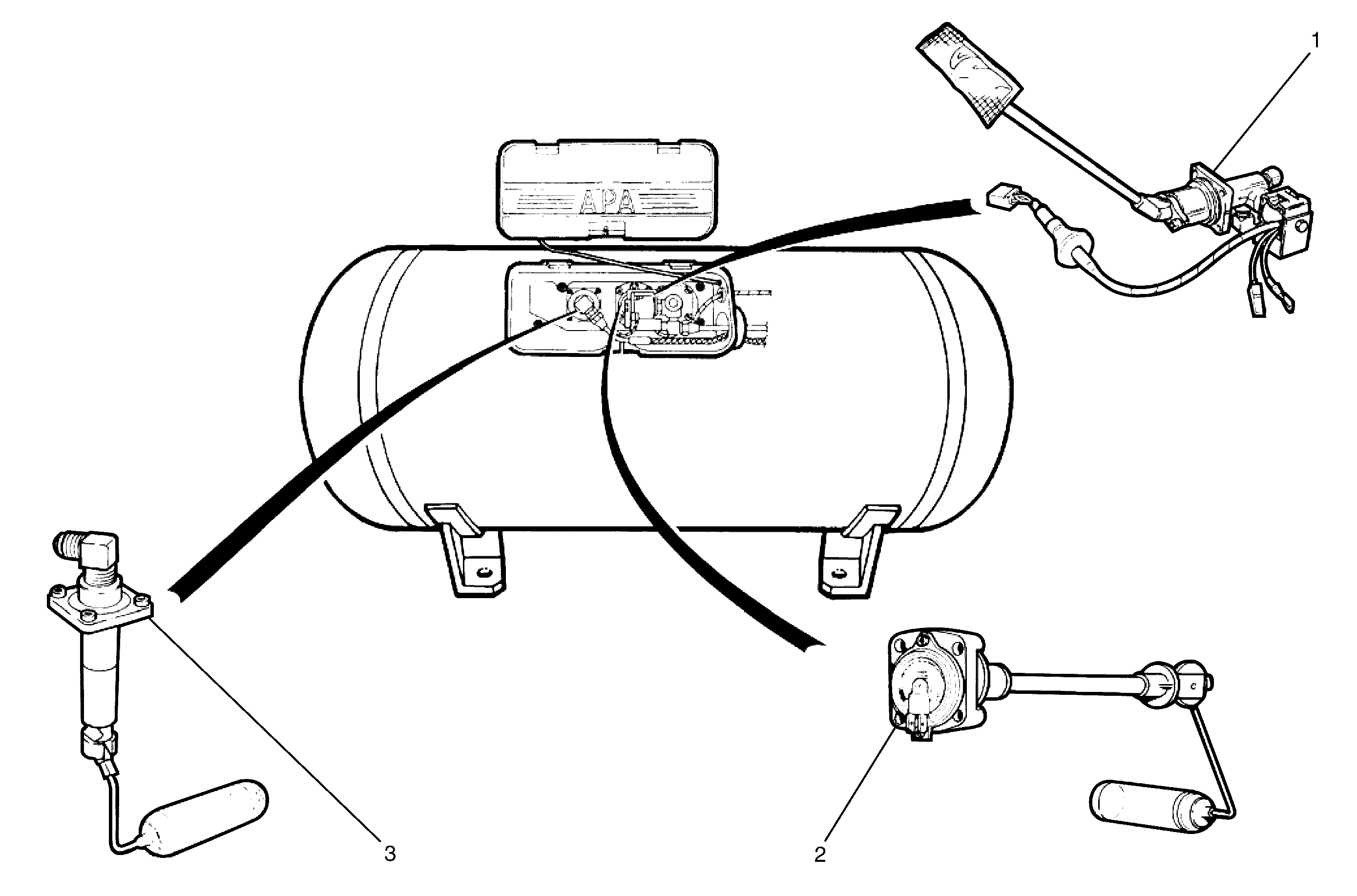
LPG Tank

LPG Tank Components


Object Number: 2082595  Size: LF
(1)Rear Lock-Off/Service Solenoid Valve Assembly and Excess Flow Valve
(2)Tank Fuel Gauge Assembly
(3)Automatic Fill Limiter (AFL)

The LPG Tank is made of carbon steel and is manufactured to stringent safety standards. LPG must be stored at approximately 750 kPa at 20°C to remain a liquid. The vapour pressure inside the LPG tank will vary with ambient temperature - as the ambient temperature rises, so does the vapour pressure. The LPG tank is heat treated during manufacture and MUST NOT be heated or welded in any way.

The LPG tank is fitted in the rear compartment, under the rear parcel shelf. The LPG tank incorporates a gas-tight compartment (valve box) which is vented to atmosphere via a vent hose and contains the following components:

    • Pressure relief valve.
    • Rear lock-off/service solenoid valve assembly and excess flow valve.
    • Tank fuel gauge assembly, and Automatic fill limiter (AFL).

These components are either attached into or onto the LPG tank. As the LPG tank is located in the luggage compartment, if any of these components were to leak, or there was an excess pressure discharge, the LPG would be vented to atmosphere via the vent hose and will not vent into the vehicle.

Filler Valve


Object Number: 2082597  Size: SH

The filler valve is located in the fuel filler pocket, adjacent to the petrol filler.

The valve incorporates two spring-loaded non-return valves (3 & 4) and a sealed cap (1) fitted to the filling connection (2).

The connection is designed to shear off in the event of the vehicle being driven away with the filler hose inadvertently attached. In this situation, the lower valve remains intact, avoiding the LPG discharging.

The filler valve is connected to the LPG tank AFL inlet elbow by a filler line, which is routed through the LPG tank vent hose.

Automatic Fill Limiter


Object Number: 2082598  Size: SH

The Automatic Fill Limiter (AFL) is fitted into the LPG tank. The inlet elbow (1) connects the to the LPG filler line.

When the tank is being filled with liquid LPG, the AFL float (5) rises with the liquid within the LPG tank. The float arm is connected to an actuator (4) that operates a shut-off piston (3). When the level reaches approximately 80% full, the piston (3) is in the closed position, effectively shutting off the flow of LPG into the tank.

The remaining 20% of the tank volume is necessary vapour space to allow for the expansion of the liquid that occurs as the temperature of the liquid increases.

The AFL is also fitted with a non-return valve (2) to prevent the gas escaping.

Rear Lock-Off/Service Solenoid Valve Assembly


Object Number: 2082599  Size: SH

The rear lock-off/service solenoid valve assembly is fitted to the LPG tank and is four valves in one, it contains the following valves:

    • Manual shut off valve.
    • Electrically operated solenoid valve.
    • Excess flow valve.
    • Pressure relief valve.

Manual Shut-Off Valve

The manual shut off valve (3) allows the supply of LPG to be manually shut off for servicing, a leak in the system develops or in the event of a vehicle accident by turning the knob (2).

Solenoid Valve

The solenoid valve (1) is an electrically operated valve, which allows the flow of LPG from the tank into the service line. The solenoid valve is energised for three seconds when the ignition key is first turned on, or constantly while the engine is being cranked or is running.

The solenoid valve (1) will shut off the LPG flow when the ignition is switched off and/or the engine stops running.

Excess Flow Valve

The excess flow valve (4) will close automatically if the flow of liquid LPG is excessive, shutting off the supply of liquid LPG. The valve will automatically reopen when the excess flow condition has ceased.

The excess flow valve is designed to shut off if the flow exceeds a specified amount, as would occur if the service line was severed or opened.

Pressure Relief Valve

If pressure within the LPG tank exceeds approximately 2,550 kPa, the valve (4) opens, overcoming spring tension. The excess pressure will then be vented into the valve box through the orifice (5) and then to atmosphere via the vent hose.

The valve will continue to vent the LPG tank until the pressure drops below 2,550 kPa and the spring closes the valve.

During normal operating conditions the pressure relief valve should not operate.

LPG Tank Fuel Gauge Assembly


Object Number: 2082600  Size: SH

The tank fuel gauge assembly (1, typical) has a float (2) similar to a petrol gauge sender unit, and a fuel contents gauge (3).

As the liquid level in the LPG tank rises, so too does the float. The float is connected to a magnet within the assembly. Any change in the position of the liquid level is transmitted to the fuel contents gauge via the float and magnet.

The magnetic field produced by the magnet causes the fuel contents gauge mounted on the exterior of the tank to move in relation to the magnet's position.


Object Number: 2082601  Size: SH

The fuel contents gauge (1) will show full when the liquid level in the tank is at 80% (2). It will show empty when the tank contents falls to approximately 8.5 litres (3).

The fuel gauge sender unit within the fuel contents gauge, incorporates a variable resistor that will vary its resistance from approximately 0 ohms when the tank is empty to approximately 90 ohms when the tank is full.

This change in resistance is used by the LPG control module to determine how many of the fuel level LED’s will be activated in the fuel selector switch and fuel level control indicators. When the vehicle is switched to petrol operation, the contents of the petrol tank will be displayed on the instrument cluster.

LPG Front Lock-Off


Object Number: 2082603  Size: SH

The LPG front lock-off is an electrically operated solenoid valve, which allows or prevents the flow of liquid LPG to the reducer when energised or de-energised by the LPG control module.

The LPG lock-off is energised for three seconds when the ignition is turned on, or constantly while the engine is being cranked or is running.

A filter is incorporated into the design, that is to be serviced every 120,000 km.

When the engine stops running, or the ignition is turned off, the LPG control module de-energises the LPG front lock-off and the supply of LPG is shut off.

Service Line


Object Number: 2082604  Size: LF
(1)Rear Service Line
(2)Intermediate Service Line
(3)Front Service Line

The service line carries the liquid LPG from the manual service valve at the LPG storage tank to the LPG lock-off. The service line consists of three major components: the front (3), intermediate (2) and rear (1) service line.

Reducer

Construction

The reducer (also known as a converter) functions are to:

    • Control the flow of liquid LPG into the reducer.
    • Provide a heat sink to allow vaporisation of the LPG and to prevent icing because of the temperature drop with the volume increase.
    • Regulate the output pressure to suit engine requirements.

Object Number: 2082605  Size: LF

Figure 8A2 -0 21 shows the three sectioned views that follow

Referring to sectioned view "A-A", the Reducer comprises the lower (18) and upper (4) bodies, with an intermediate plate (11), separated by two gaskets (19) and (21).

The upper body (4), contains the pressure regulator spring (1) contained between the upper (2) and lower (6) caps, the upper one of which is adjustable via an externally adjustable screw (3). The diaphragm, located between the upper body and intermediate plate is supported by a small plate (10) and the lower spring cap (6). The upper end of the control shaft (16) is connected to the diaphragm, the two small support plates and Bauer spring (7) by a self-locking nut (5).

Also installed into the upper plate is a fitting (8) for the fitment of a small tube, sensing the engine intake manifold vacuum (or absolute pressure). Also included in the upper plate is a regulating pressure valve (refer to Figure 8A2 - 23 for detail of this valve).

The lower plate contains the primary valve (14) and priming valve pivoting arm (15), connected to the lower end of the control shaft (16). A fitting (13) for the high pressure liquid LPG is provided and the two fittings (12) for the engine coolant (only one is shown in this sectioned view.

Both plates are provided with channels (17) to allow engine coolant to flow around the assembly, with the heat being transferred to the very cold vapour, raising its temperature (and pressure). The Intermediate plate plugged drain (20) in the intermediate plate (11) allows movement of the LPG vapour from the lower (18) to the upper (4) plates.

To summarise, the flow of liquid LPG into the reducer is regulated by the priming valve (14) that is controlled by the vertical movement of the control shaft (16) acting on the priming valve pivot arm (15). The control shaft (16) is connected at the upper end, to the diaphragm separating the upper body (4) and the intermediate plate (11).

Reducer (Section A - A)


Object Number: 2082606  Size: LF
(1)Pressure Regulation Spring
(2)Upper Spring Cap
(3)Spring Tension Adjusting Screw
(4)Upper Body
(5)Control Shaft Nut
(6)Lower Spring Cap
(7)Bauer Spring
(8)Intake Manifold Pressure Fitting
(9)Temperature Sensor
(10)Lower Diaphragm Support Plate
(11)Intermediate Plate
(12)Engine Coolant Fitting (2 of)
(13)LPG Liquid Input Fitting
(14)Primary Valve
(15)Primary Valve Pivot Arm
(16)Control Shaft
(17)Coolant Channel
(18)Lower Body
(19)Gasket
(20)Intermediate Plate Plugged Drain
(21)Gasket
(22)LPG Vapour Output Fitting

Operation

The conversion of the high pressure liquid LPG coming from the front LPG lock-off to a low pressure, very cold vapour is controlled by the primary valve (14). In turn, the opening of the primary valve is controlled by the vertical movement of the control shaft (16) acting on the primary valve pivot arm (15), that pivots about the pin, anchored to the lower body (18).

In the process of rapidly reducing the pressure from approximately 1,260 kPa in the tank to atmospheric (101.3 kPa), the liquid LPG changes state to become a vapour and this causes a rapid reduction in temperature. To compensate for this and to assist in vaporisation, engine coolant circulates through the heat exchanger channels (17) in the upper and lower bodies. The reducer seals off LPG flow when the engine is stopped.

The pressure regulating spring (1), acting on the upper side of the diaphragm (6), pushes the diaphragm down. This opens the primary valve (14), allowing LPG to enter the reducer and then to flow through the heat exchanger (17) where the LPG changes state from a liquid to a vapour.

When the engine is cranked or running, a vacuum is created in the engine intake manifold that is transmitted to one end of the reducer by tubing screwed onto the fitting (8). This tube is connected to a ‘T’ piece in the vacuum line and also connected to the P1 MAP sensor. The effect of this vacuum is to work against the regulating spring force, together with the pressure of the LPG acting on the underneath side of the primary diaphragm. This combined action achieves a balance on each side of the diaphragm.

LPG released from the reducer flows through to the vapour filter, before being delivered to each LPG injector manifold by tubing.

Pressure Limit Valve (Section B - B)


Object Number: 2082607  Size: LF

The pressure limiting device consists of the body (5) that is screwed into the reducer upper plate and sealed by O-rings (1 and 2). The adjustment screw (3) that preloads the spring (4) and the piston (6), also sealed by an O-ring (1). At the end of the piston is a seal (7) that seals the sensed LPG pressure.

Should the LPG vapour pressure rise beyond the pre-set value, the piston seal (6) will be lifted off its seat by the LPG pressure, allowing excess vapour to be vented internally into the output stage of the reducer. In this way, no LPG resulting from this pressure control, is released into the atmosphere.

Important: Under no circumstances is the spring force of the pressure limit valve to be tampered with or altered.

Fitment of this valve is purely as a precaution as it is very rarely required to operate. Should it be activated however, it would only be for a very short time and no LPG vapour enters the engine compartment.

Temperature Sensor (Section C -- C)


Object Number: 2082608  Size: LF

Section C - C shows the location of the NTC resistance, temperature sensor (5) that is located in the outlet stage of the reducer. Until the exiting LPG vapour reaches a prescribed temperature, the LPG ECU will keep the engine running on petrol, regardless of the fuel switch position.

In this way, running on LPG is not possible until the engine coolant reaches a pre-determined temperature.

The outlet fitting (1) and the temperature sensor (5) are sealed by O-rings (3 and 6). The bolts (2) clamping the reducer upper and lower bodies together are sealed by O-Rings (4) under each of the bolt heads.

LPG Control Module


Object Number: 2082609  Size: LF

The LPG Electronic Control Unit (ECU), controls the two operating modes: Petrol or LPG.

Petrol Mode

When operating in petrol mode, the LPG ECU signals the smart unit at the LPG tank to stop LPG flow. At the same time, the front LPG Lock-Off solenoid is also de-energised, further preventing LPG flow to the reducer. As the emulator signal is not used in this situation, the vehicle then operates on petrol with full engine management control from the engine ECU. The engine then operates in the same way that a single fuelled petrol engine would do. In this mode, the instrument cluster fuel gauge will show the amount of petrol in the petrol fuel tank.

LPG Mode

When operating in the LPG mode, the ECU energises the Smart Unit and the Front Lock-Off solenoid, allowing LPG to flow to the ‘Genius Max’ reducer. The engine switch-over to LPG however, will not occur until engine temperature is high enough to provide adequate vaporisation of the LPG

Once the temperature is up to the pre-determined level, the LPG ECU will activate the emulators and the engine ECM will then control the pulse width of the LPG injectors.

When operating in LPG mode under conditions of prolonged high speed / high load operation, a small amount of petrol is injected into the engine to cool the valves and catalytic reducer.

Vapour Filters


Object Number: 2082611  Size: SH

The vapour filter (2) is mounted to a bracket (4) and secured to the mounting bracket by a nut and washer.

Exiting LPG vapour from the reducer passes through the vapour filter and vapour lines (1 & 3) and then to each of the LPG injector manifolds.

Servicing of the vapour filter is by replacement, every 15,000 km.

LPG Fuel Injectors


Object Number: 2082613  Size: LF

The BRC LPG injectors are referred to as a ‘bottom feed’ type because the injector is fully immersed in the gas manifold.

When the injector solenoid is energised, the internal valve is lifted from its seat against an internal spring force, by an electro-magnet. This action allows gas to be injected into the engine intake manifold, via a hose.

At the base of the internal valve is a rubber seal, to ensure reliable sealing.

The injector voltage supply is referred to as ‘peak and hold’. This means that battery voltage is applied to the electromagnet to effect a rapid opening and then varied to maintain the valve in an open position.

The injector open time is controlled by the engine ECM as previously described.

The injector coil resistance is 1.8Ω @ 20° C.