For 1990-2009 cars only
Removal Procedure
- Raise and support the vehicle. Refer to Lifting and Jacking the Vehicle .
- Turn the steering wheel to the straight-ahead position. Ensure the front tires are in the straight-ahead position.
- Remove the front tire and wheel assemblies. Refer to Tire and Wheel Removal and Installation .
- Place a drain pan under the power steering gear in order to catch the power steering fluid.
- Remove the power steering pipes from the steering gear. Refer to Steering Gear Replacement .
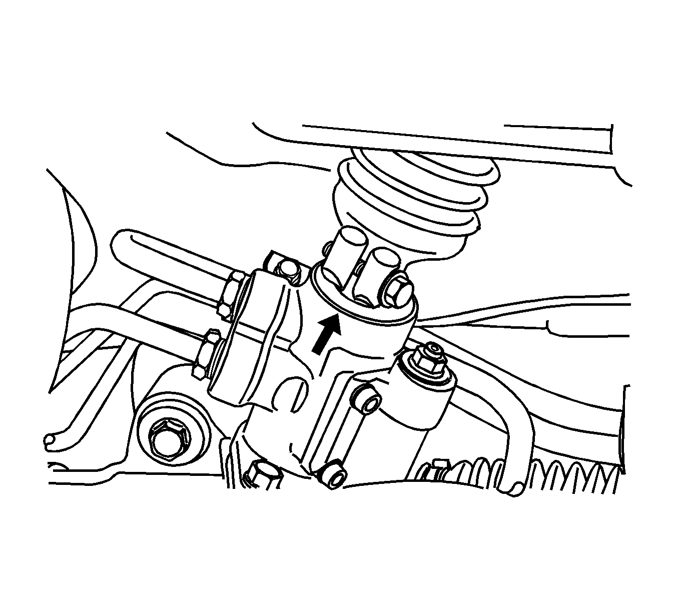
- Place a match mark on the stub shaft housing that lines up with the groove of the intermediate shaft. This mark will be used for proper alignment during installation.
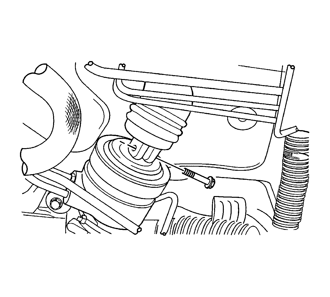
- Remove the lower pinch bolt from the universal joint on the intermediate shaft.
- If the vehicle has a manual transaxle, remove the gear shift control bracket and fixing clip.
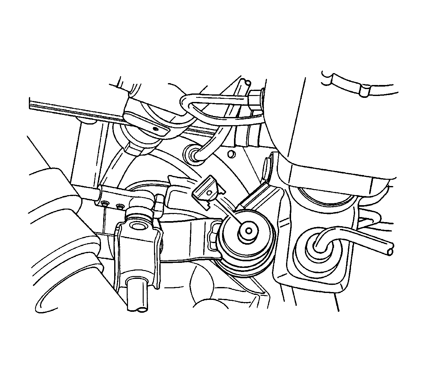
- Remove the center member. Refer to Engine Front Crossmember Replacement .
- Remove the front exhaust pipe. Refer to Front Pipe Replacement .
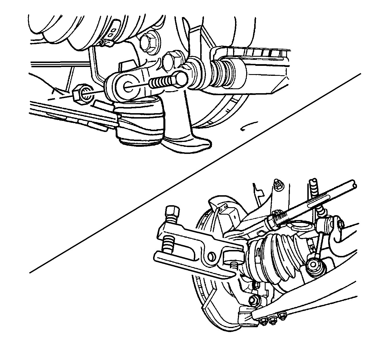
- Separate the outer tie rod from the steering knuckle. Refer to Rack and Pinion Outer Tie Rod End Replacement .
- Separate the control arm ball joint from the steering knuckle. Refer to Control Arm Replacement .
- Remove the crossmember bolts-to-control arm and nuts-to-longitudinal frame.
- Lower the crossmember.
- Remove the power steering gear from the crossmember assembly. Refer to Steering Gear Replacement .
- Remove the stabilizer shaft from the crossmember assembly. Refer to Stabilizer Shaft Replacement .
- Remove the control arm from the crossmember assembly. Refer to Control Arm Replacement .
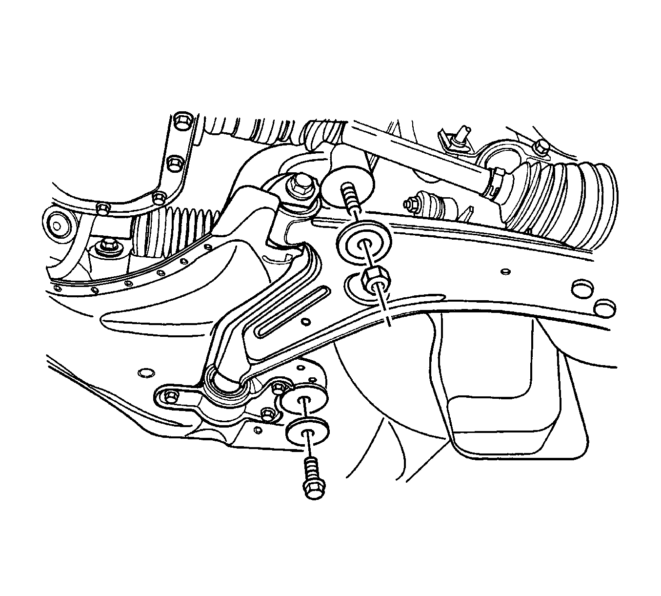
Caution: Failure to support crossmember can cause crossmember to drop to the ground when crossmember mounting bolts are removed.
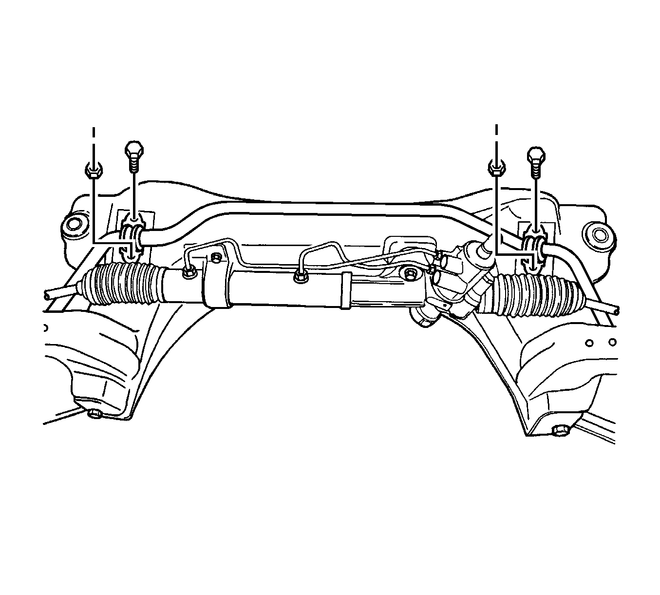
Installation Procedure
- Install the control arm to the crossmember assembly. Refer to Control Arm Replacement .
- Install the stabilizer shaft to the crossmember assembly. Refer to Stabilizer Shaft Replacement .
- Install the power steering gear to the crossmember assembly. Refer to Steering Gear Replacement .
- Raise the crossmember assembly up to the vehicle.
- Install the crossmember bolts-to-control arm, nuts-to-longitudinal frame and crossmember.
- Install the control arm ball joint to the steering knuckle. Refer to Control Arm Replacement .
- Install the outer tie rod end to the steering knuckle. Refer to Rack and Pinion Outer Tie Rod End Replacement .
- Install the front exhaust pipe. Refer to Front Pipe Replacement .
- Install the center member. Refer to Engine Front Crossmember Replacement .
- If the vehicle has a manual transaxle, install the shift control bracket and clip.
- Align the match marks on the steering shafts in order to ensure proper positioning. Seat the steering gear stub shaft into the intermediate shaft.
- Install the lower intermediate shaft pinch bolt.
- Install the power steering pipes to the steering gear. Refer to Steering Gear Replacement .
- Install the front tire and wheel assemblies. Refer to Tire and Wheel Removal and Installation .
- Lower the vehicle.
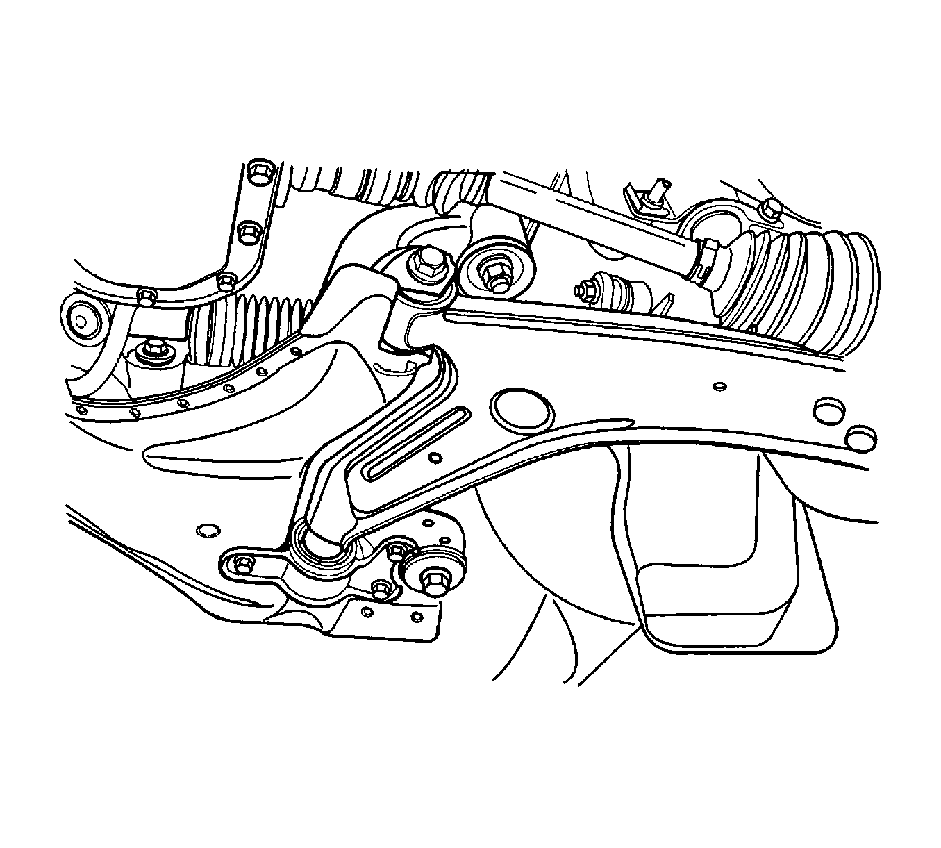
Notice: Refer to Fastener Notice in the Preface section.
Tighten
Tighten the crossmember bolts-to-control arm and nuts-to-longitudinal frame to 150 N·m (110 lb ft).


Important: The steering gear must be in the straight-ahead position.

Tighten
Tighten the intermediate shaft pinch bolt to 25 N·m (18 lb ft).
