For 1990-2009 cars only
Removal Procedure
- Remove the fuel pump fuse.
- Start the engine and repeat cranking until the remaining fuel in the fuel line is all consumed.
- Disconnect the negative battery cable.
- Drain the engine coolant. Refer to Cooling System Draining and Filling .
- Drain the engine oil.
- Drain the transaxle oil.
- Drain the power steering oil.
- Recover the refrigerant. Refer to Refrigerant Recovery and Recharging .
- Remove the engine assembly. Refer to Engine Replacement .
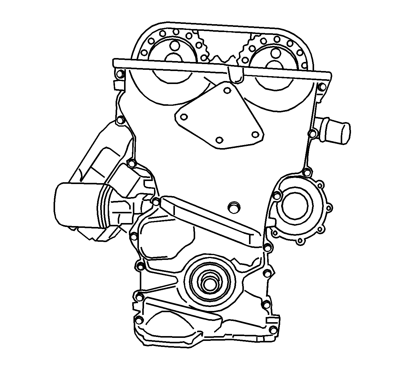
- Remove the timing chain cover. Refer to Timing Chain and Sprocket Replacement .
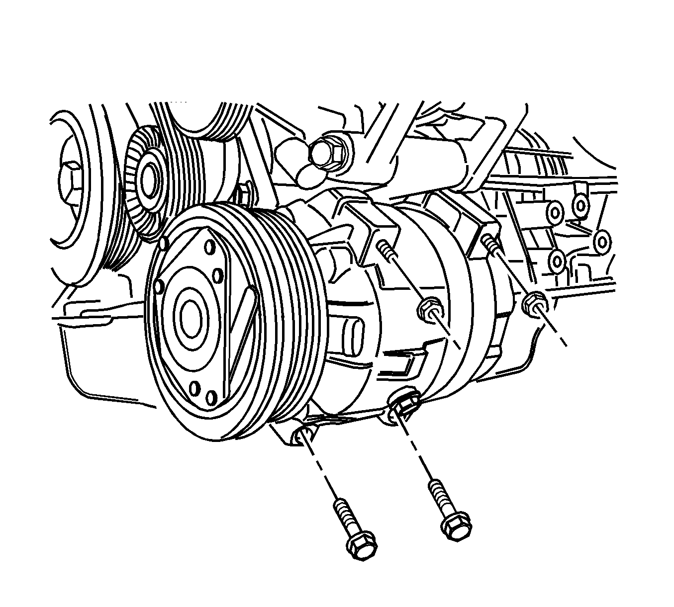
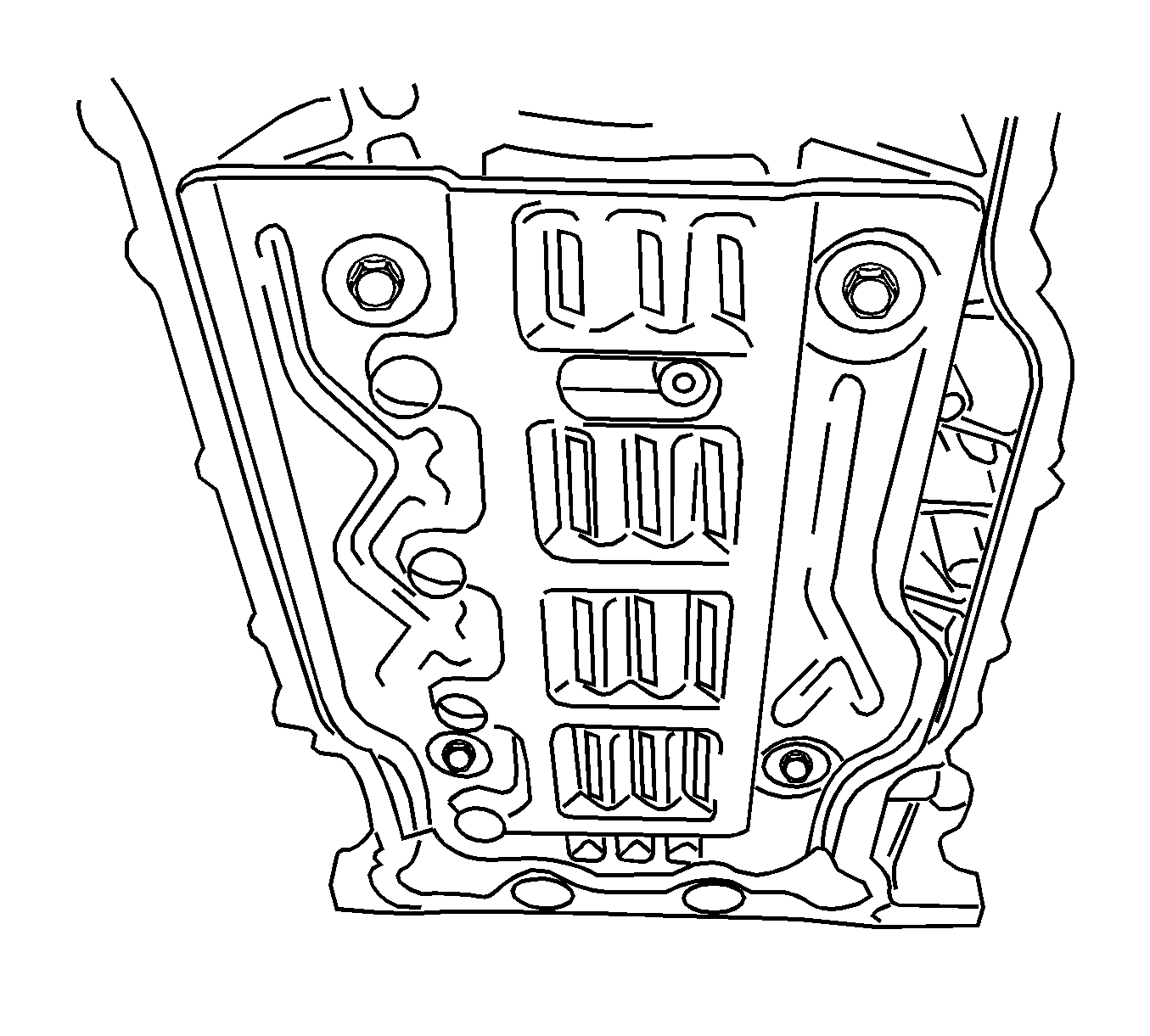
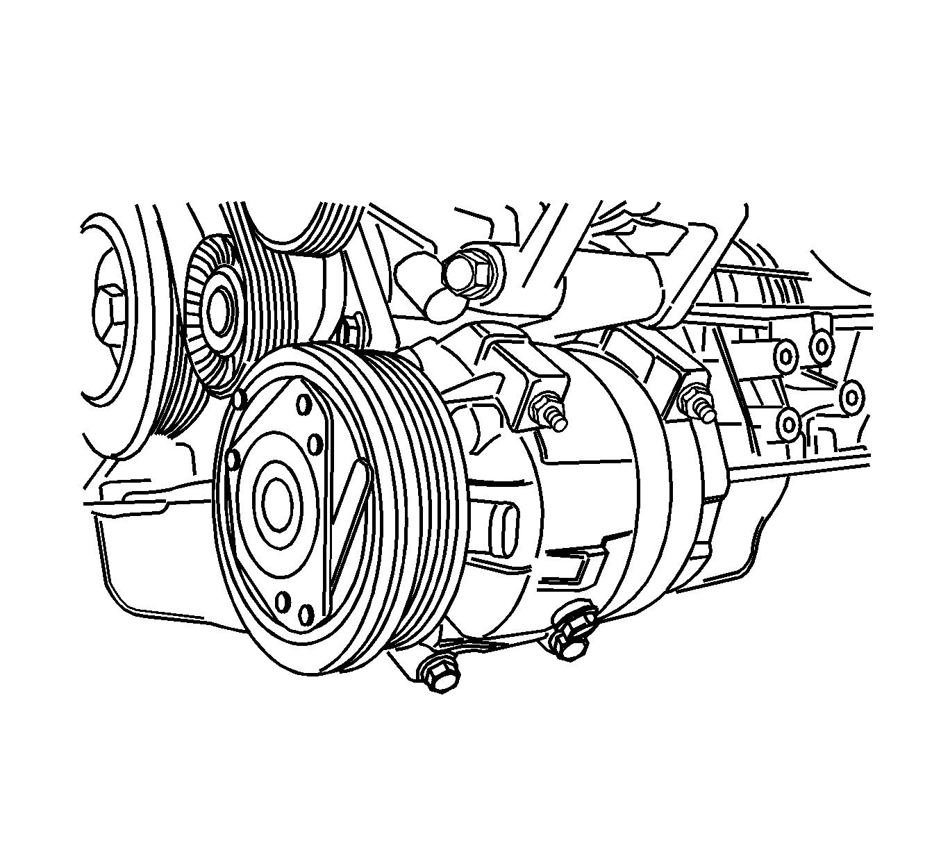
- Remove the compressor.
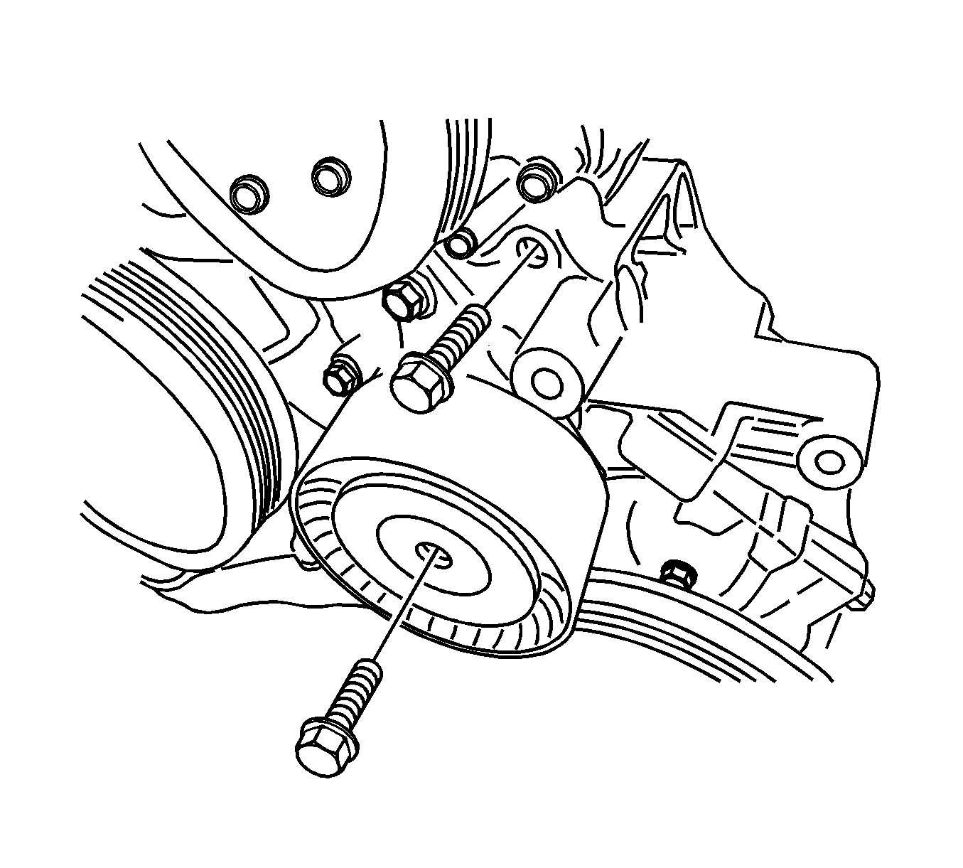
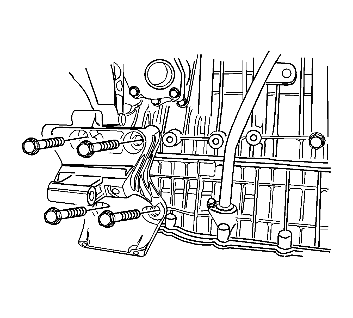
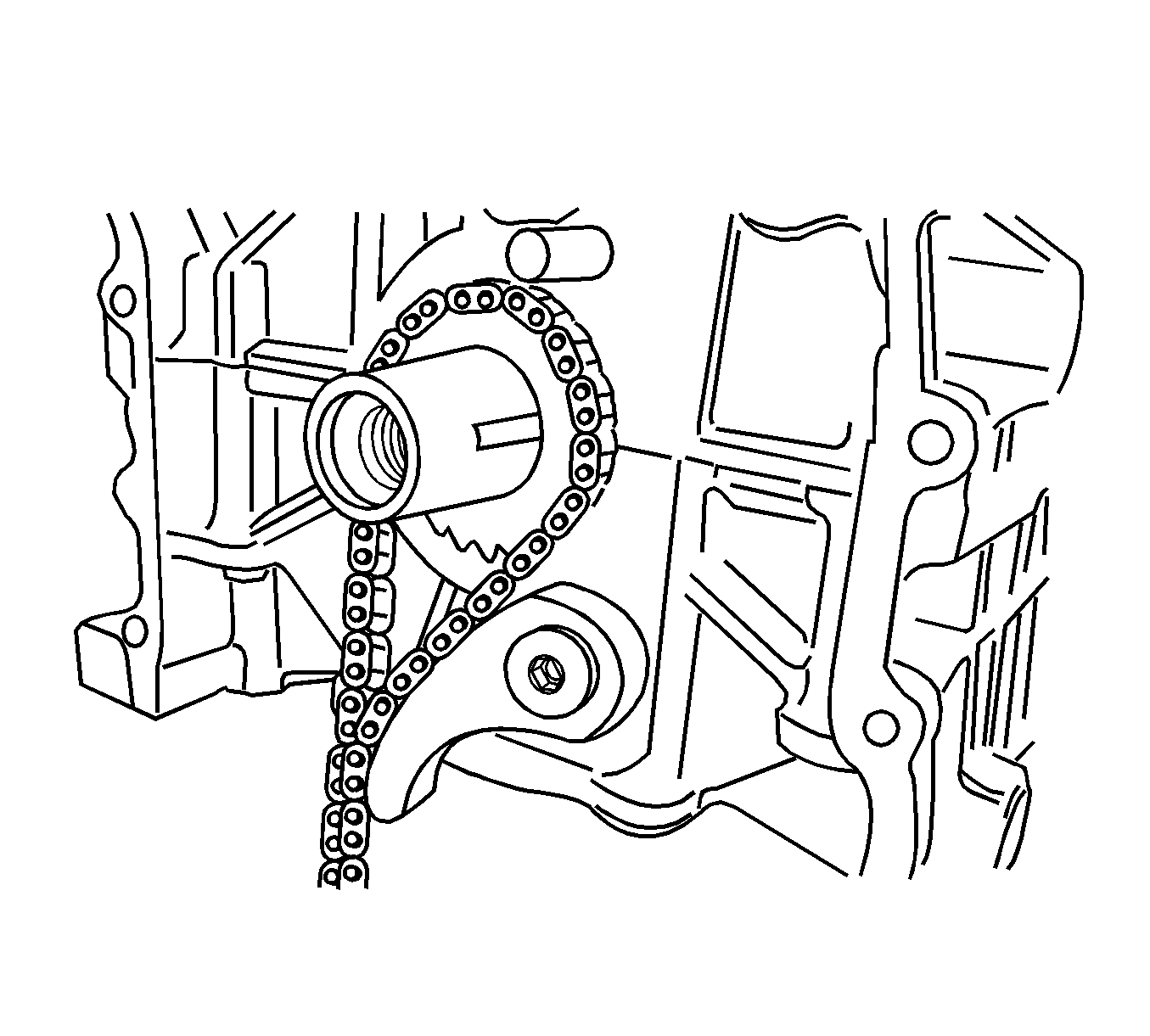
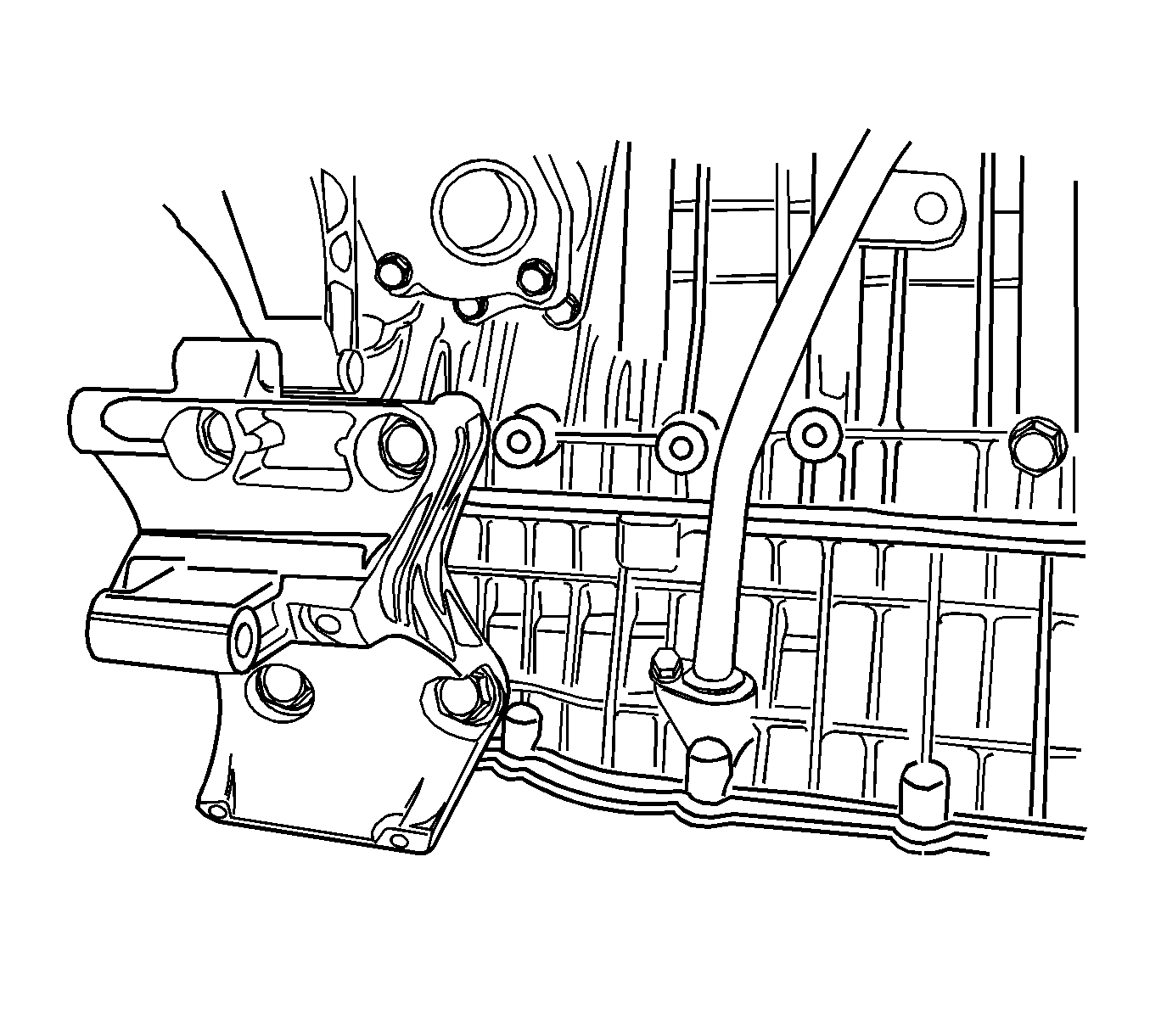
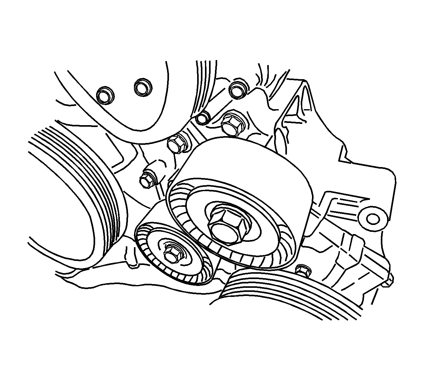
- Remove the idler retaining bolt, upper pad-to-lower pad bracket bolt, and the idler.
- Remove the lower pad bracket.
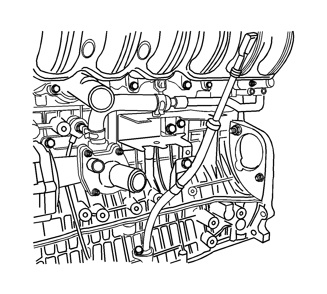
- Remove the engine oil dipstick tube.
- Remove the crankshaft position (CKP) sensor. Refer to Crankshaft Position Sensor Replacement .
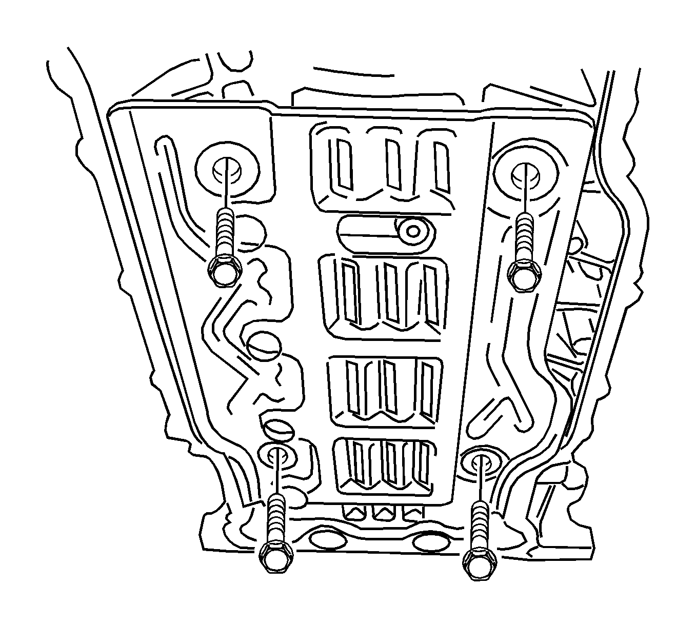
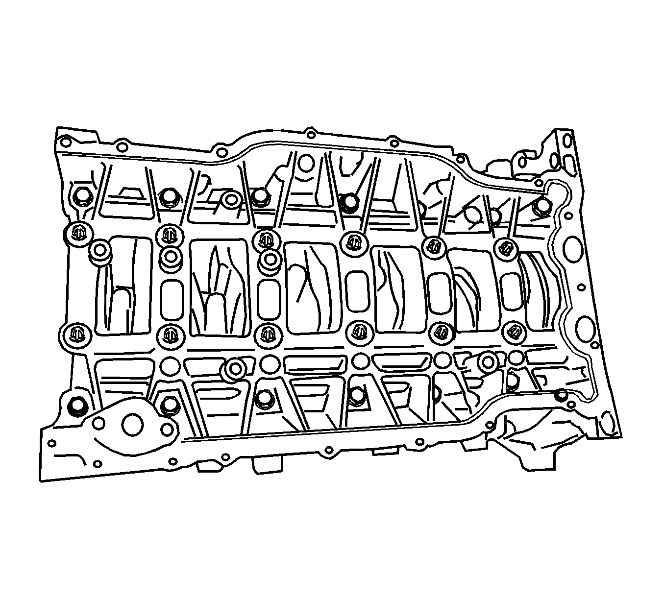
- Remove the bed plate baffle.
- Remove the oil pump chain lever.
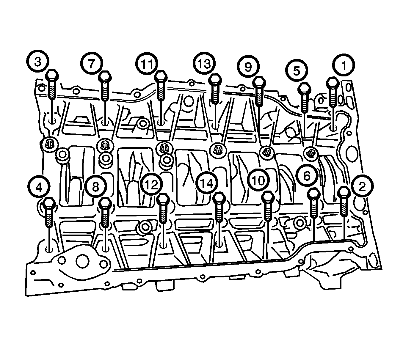
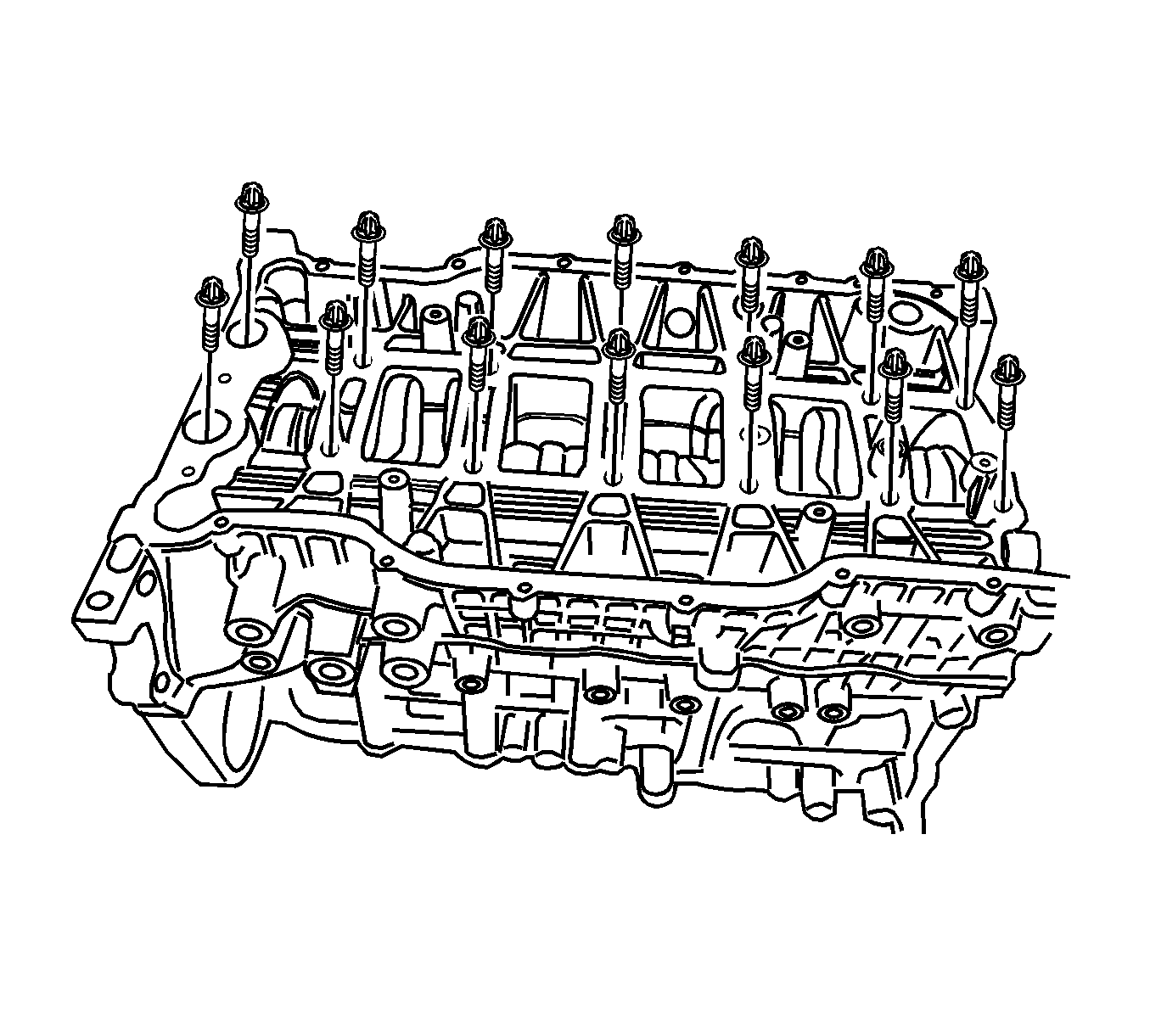
- Remove the bed plate outer bolts in the sequence shown.
- Remove the bed plate inner bolts.
Caution: Refer to Battery Disconnect Caution in the Preface section.

Installation Procedure
- Clean the contact surfaces between the bed plate and the cylinder block.
- Apply the liquid gasket, Loctite® 5900-M8585, on the bed plate.
- Install the bed plate.
- Tighten the bed plate outer bolts.
- Install the oil pump. Refer to Oil Pump Replacement .
- Install the oil pump chain lever.
- Install the bed plate baffle.
- Install the oil pan. Refer to Oil Pan Replacement .
- Install the engine oil dipstick tube.
- Install the CKP sensor. Refer to Crankshaft Position Sensor Replacement .
- Install the lower pad bracket.
- Install the idler.
- Install the compressor.
- Install the timing chain and timing chain cover. Refer to Timing Chain and Sprocket Replacement .
- Install the engine assembly. Refer to Engine Replacement .
- Install the fuel pump fuse.
- Connect the negative battery cable.
- Refill the crankcase with engine oil.
- Refill the engine coolant system. Refer to Cooling System Draining and Filling .
- Fill and bleed the power steering system. Refer to Power Steering System Bleeding .
- Refill the A/C System. Refer to Refrigerant Recovery and Recharging .

Notice: Refer to Fastener Notice in the Preface section.
Tighten
Tighten the bed plate inner bolts to 33 N·m (24 lb ft). After tightening all the inner bolts, turn the bolts by 135 degrees each.
Tighten
Tighten the bed plate outer bolts to 20-26 N·m (15-19 lb ft).
Tighten
Tighten the oil pump chain lever bolt to 8 N·m (71 lb in).
Tighten
Tighten the bed plate baffle bolts to 8 N·m (71 lb in).
Tighten
| • | Tighten the engine oil dipstick tube bracket bolt to 20 N·m (15 lb ft). |
| • | Tighten the engine oil dipstick tube bolt to 9 N·m (80 lb in). |
Tighten
Tighten the lower pad bracket bolts to 40 N·m (30 lb ft).
Tighten
| • | Tighten the idler retaining bolts to 45 N·m (33 lb ft). |
| • | Tighten the upper pad-to-lower pad bracket bolt to 35 N·m (26 lb ft). |
Tighten
Tighten the compressor retaining bolts and nuts to 25 N·m (18 lb ft).