Tools Required
| • | EN 47519 , DW117 (DW110-060) Universal Engine Support Fixture |
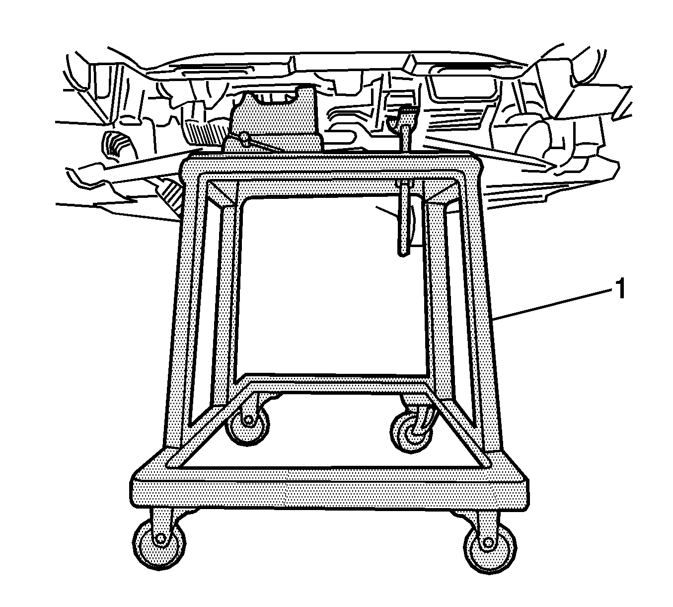
| • | J 39580 (DW010-010) Power Pack Stand Engine and Transaxle Assembly Support Remover/Installer |
| • | OTC 1726 (DW110-030) Engine Overhaul Stand |
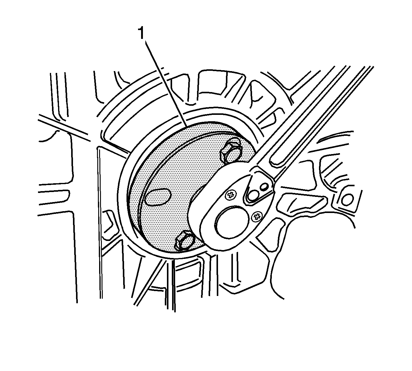
| • | EN-47610 (DW110-130-01) Crankshaft Pulley Holder |
| • | EN-47611 (DW110-130-02) Crankshaft Pulley Installer/Remover |
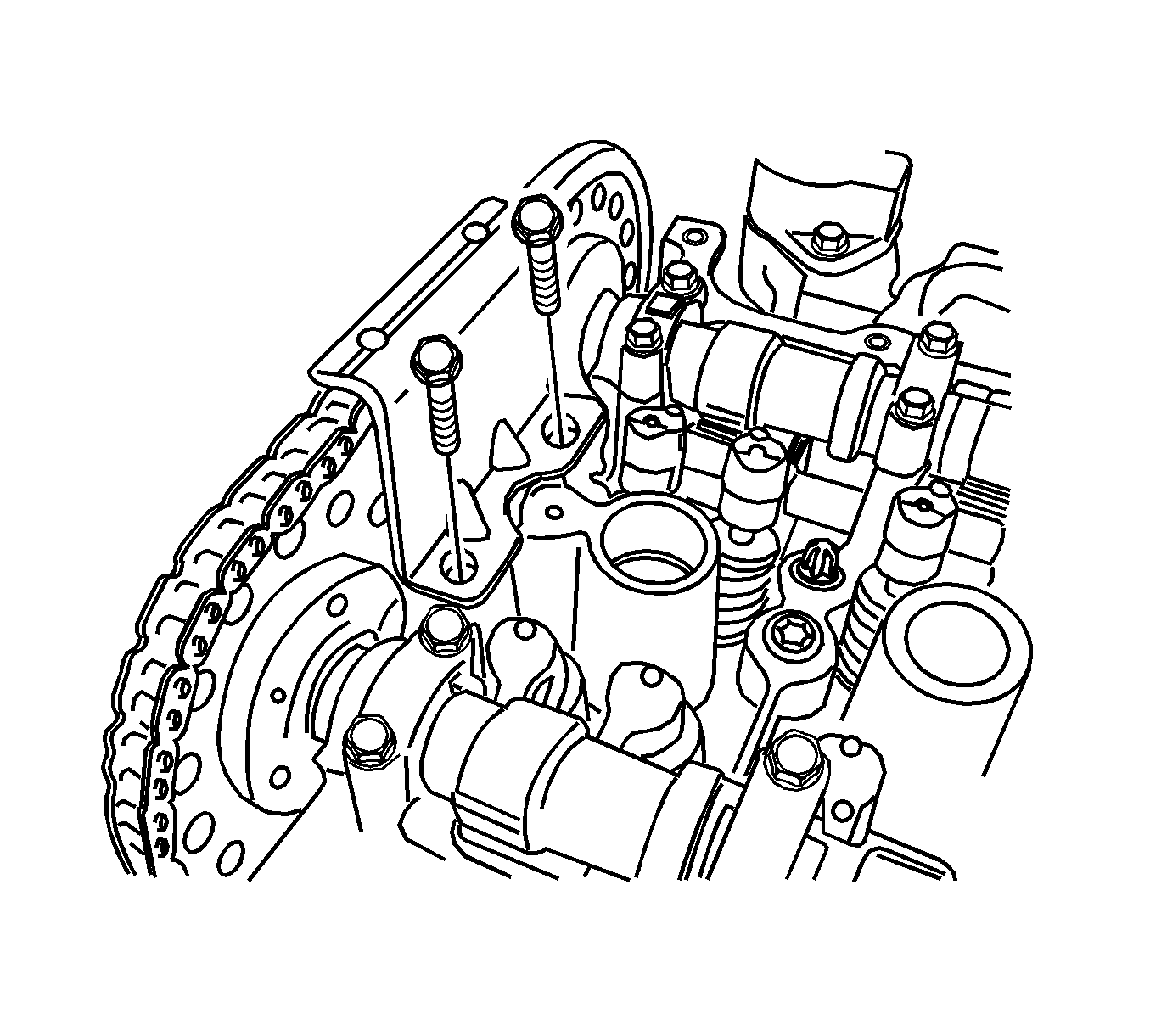
| • | EN-47612 (DW110-140) Timing Chain Cover Install Guide Pin |
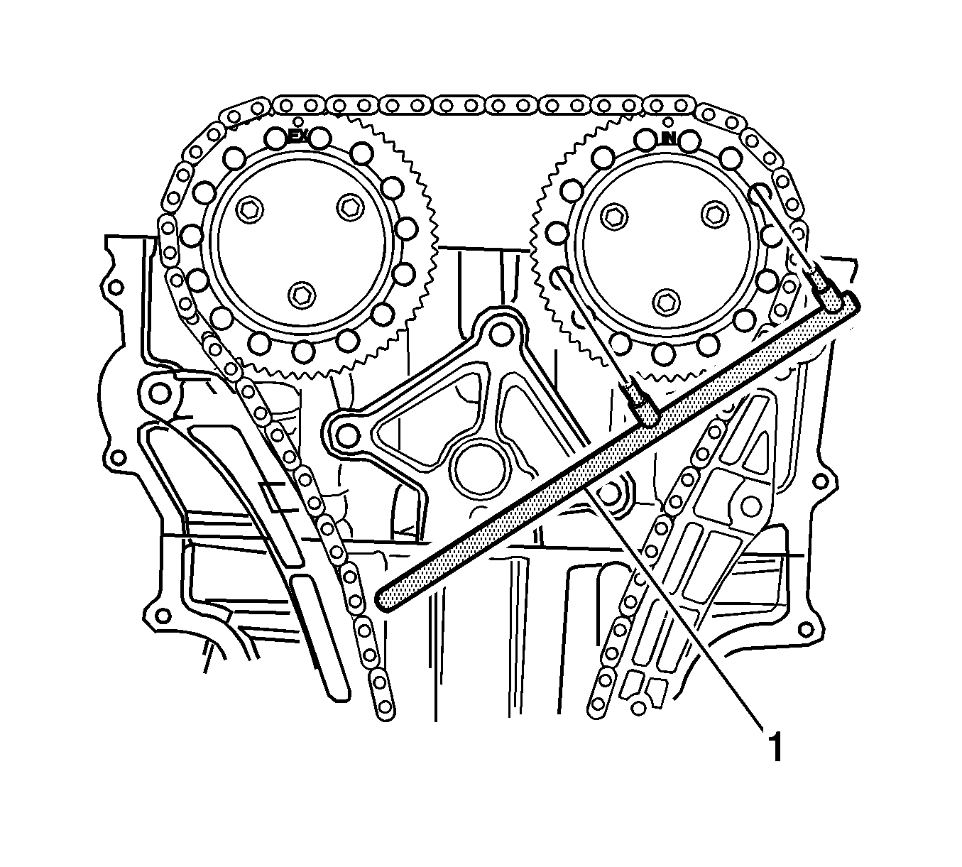
| • | EN-47613 (DW110-150) Camshaft Sprocket Holder |
| • | EN-47617 (DW110-190) Crankshaft Adjuster |
Removal Procedure
- Remove the fuel pump fuse.
- Start the engine and repeat cranking until the remaining fuel in the fuel line is all consumed.
- Disconnect the negative battery cable.
- Drain the engine coolant. Refer to Cooling System Draining and Filling .
- Drain the engine oil.
- Drain the transaxle oil.
- Drain the power steering oil.
- Recover the refrigerant. Refer to Refrigerant Recovery and Recharging .
- Remove the engine assembly using the J 39580 (1). Refer to Engine Replacement .
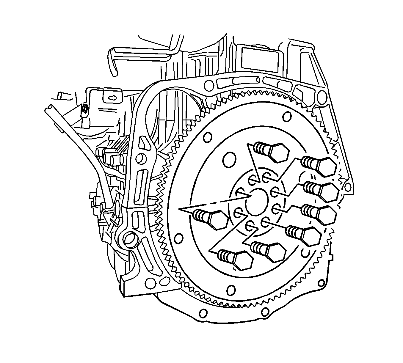
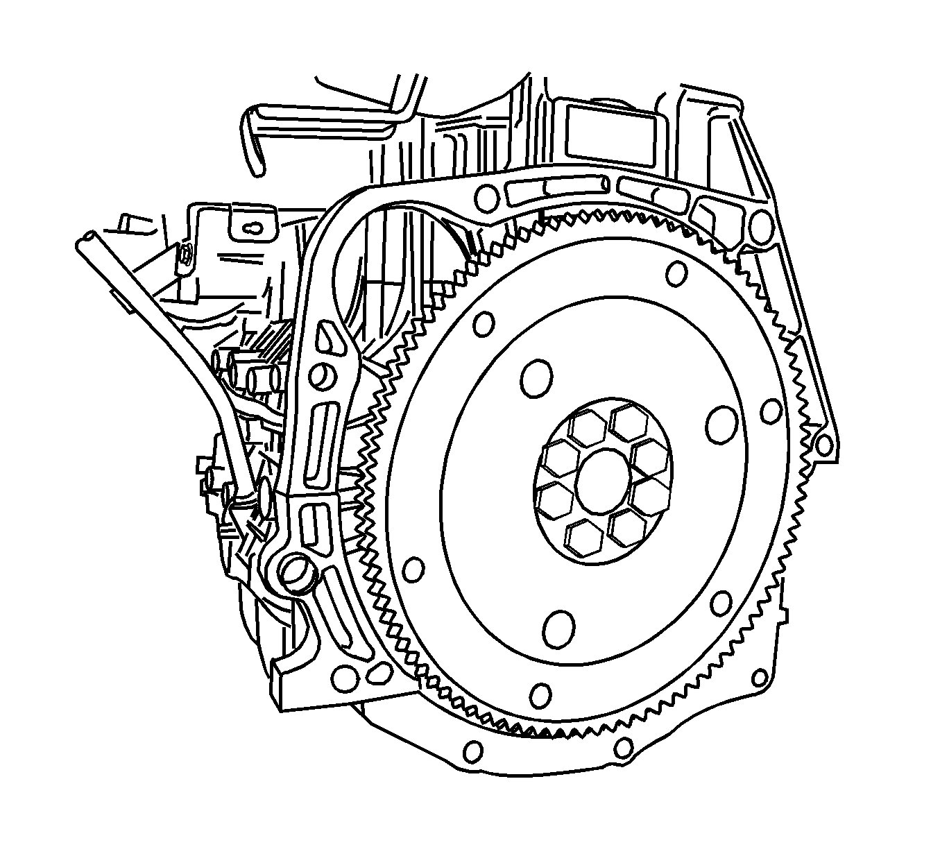
- Remove the flexible plate bolts and the flexible plate.
- Support the engine assembly with the OTC 1726 .
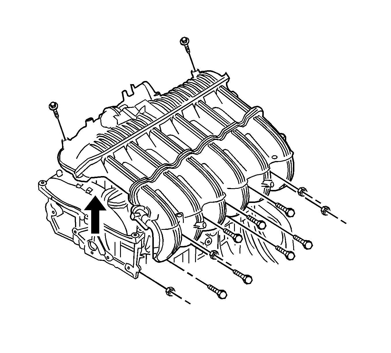
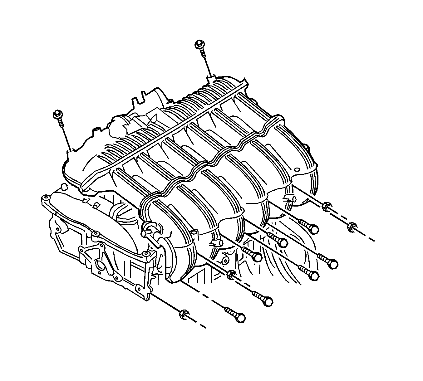
- Remove the intake manifold. Refer to Intake Manifold Replacement .
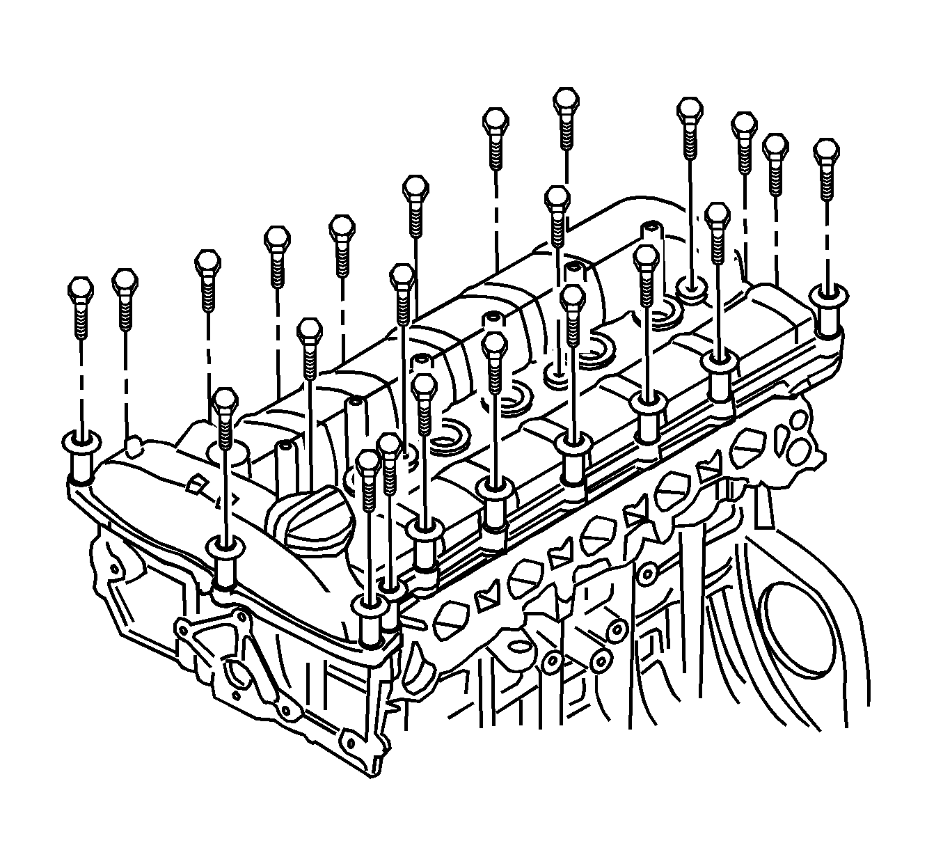
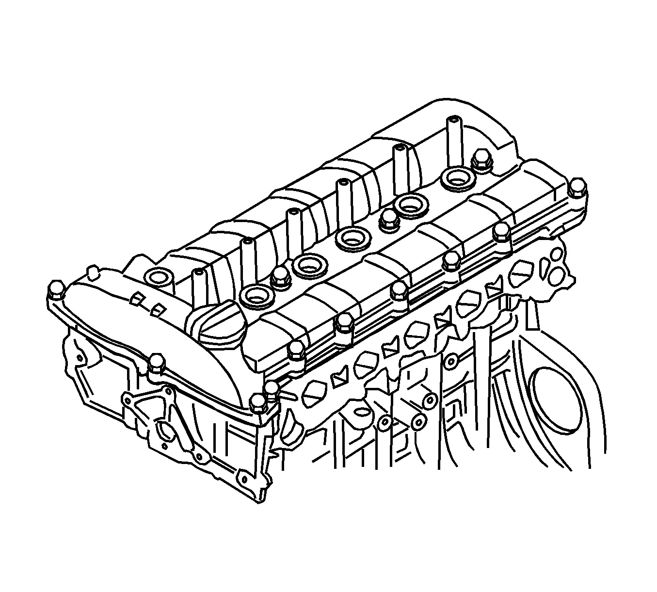
- Remove the cylinder head cover. Refer to Cylinder Head Cover Replacement .
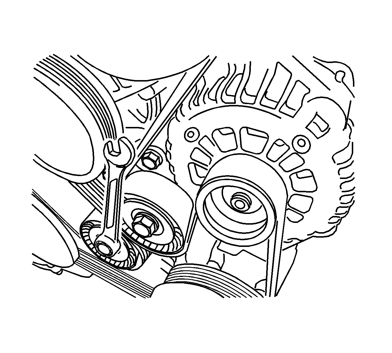
- Remove the drive belt.
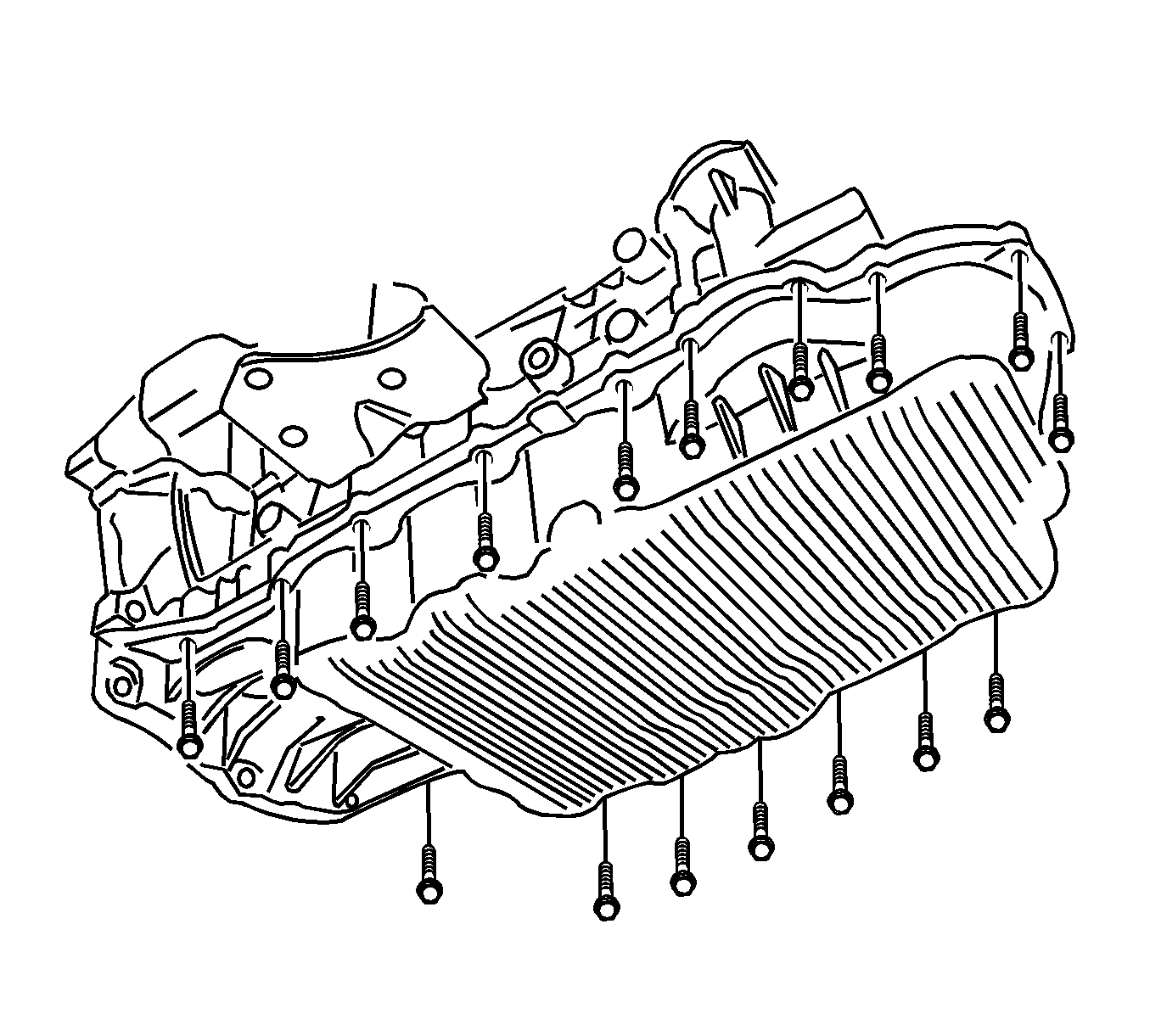
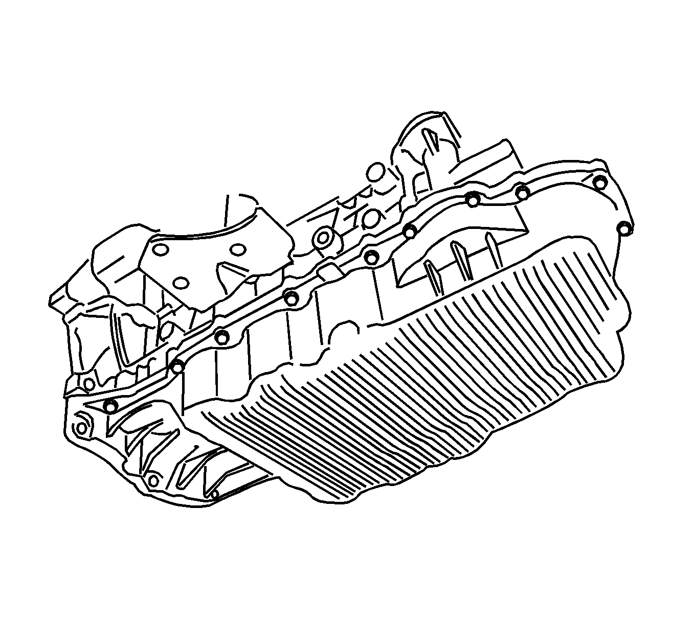
- Remove the oil pan. Refer to Oil Pan Replacement .
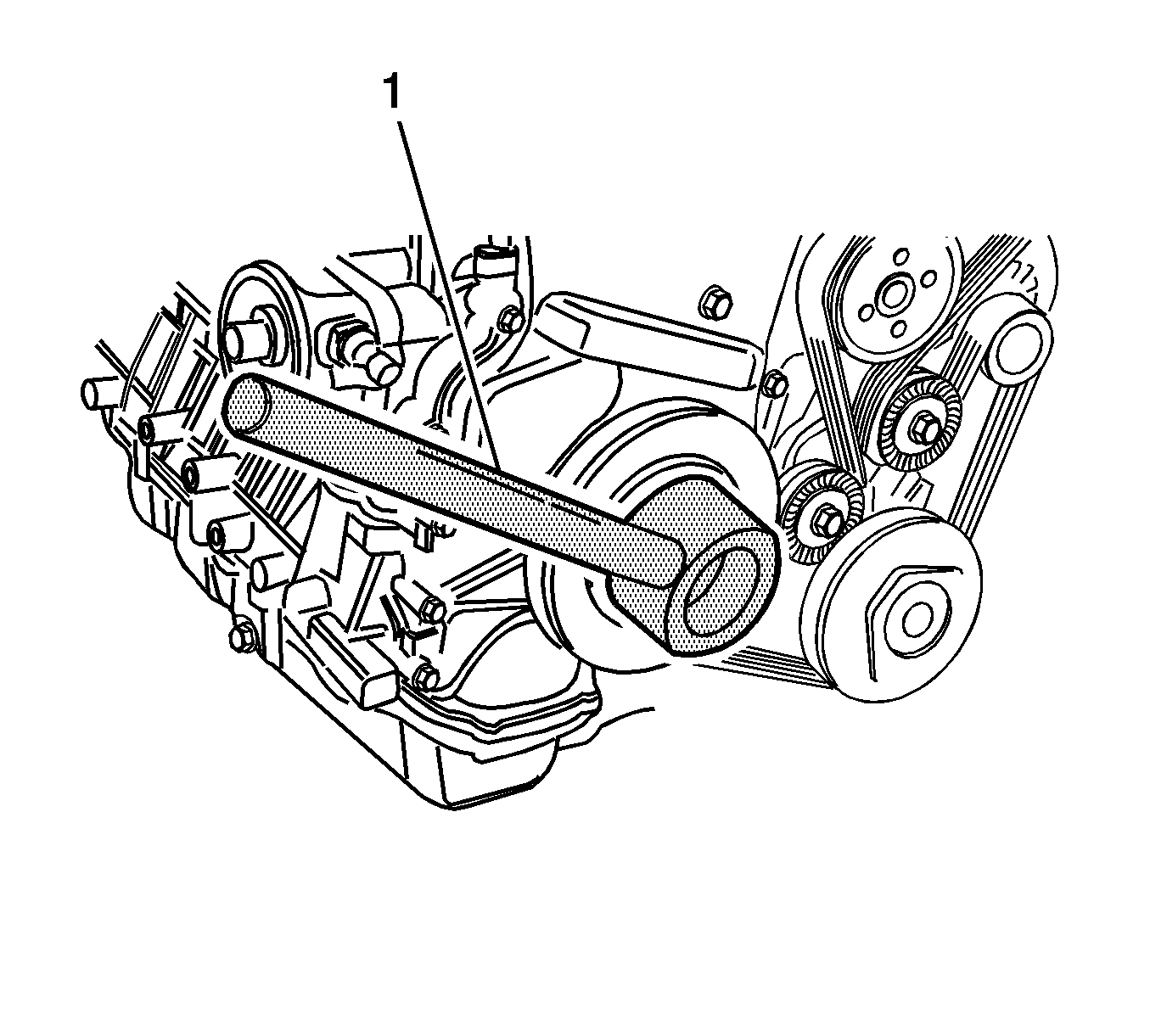
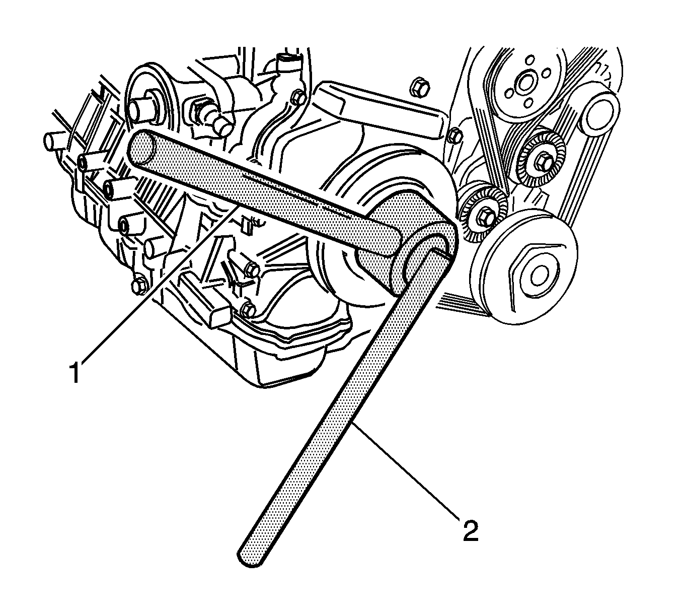
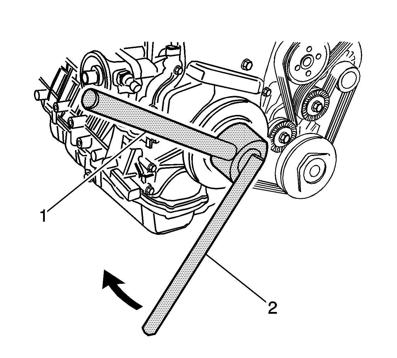
- Install the EN-47610 (1) to the crankshaft pulley bolt.
- Remove the crankshaft pulley bolt using the EN-47611 (2).
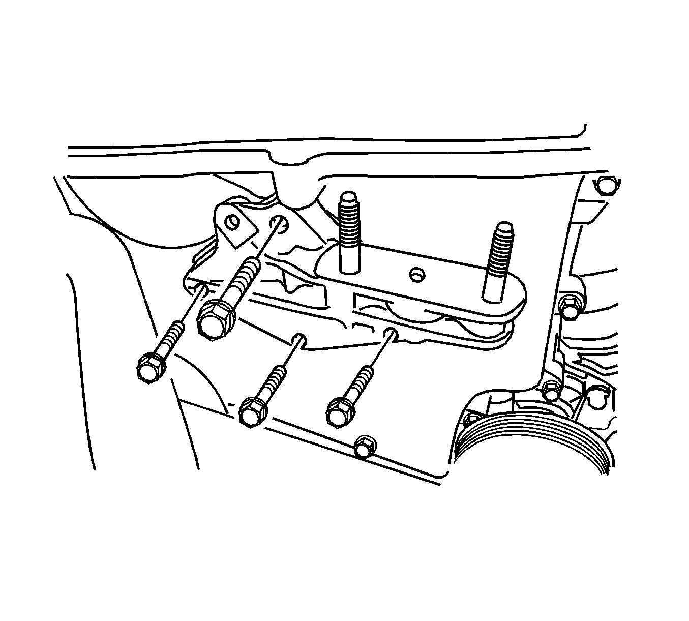
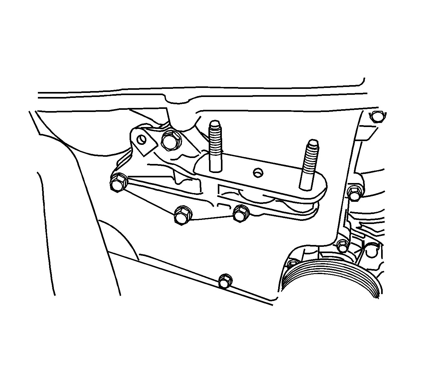
- Remove the engine mount bracket support.
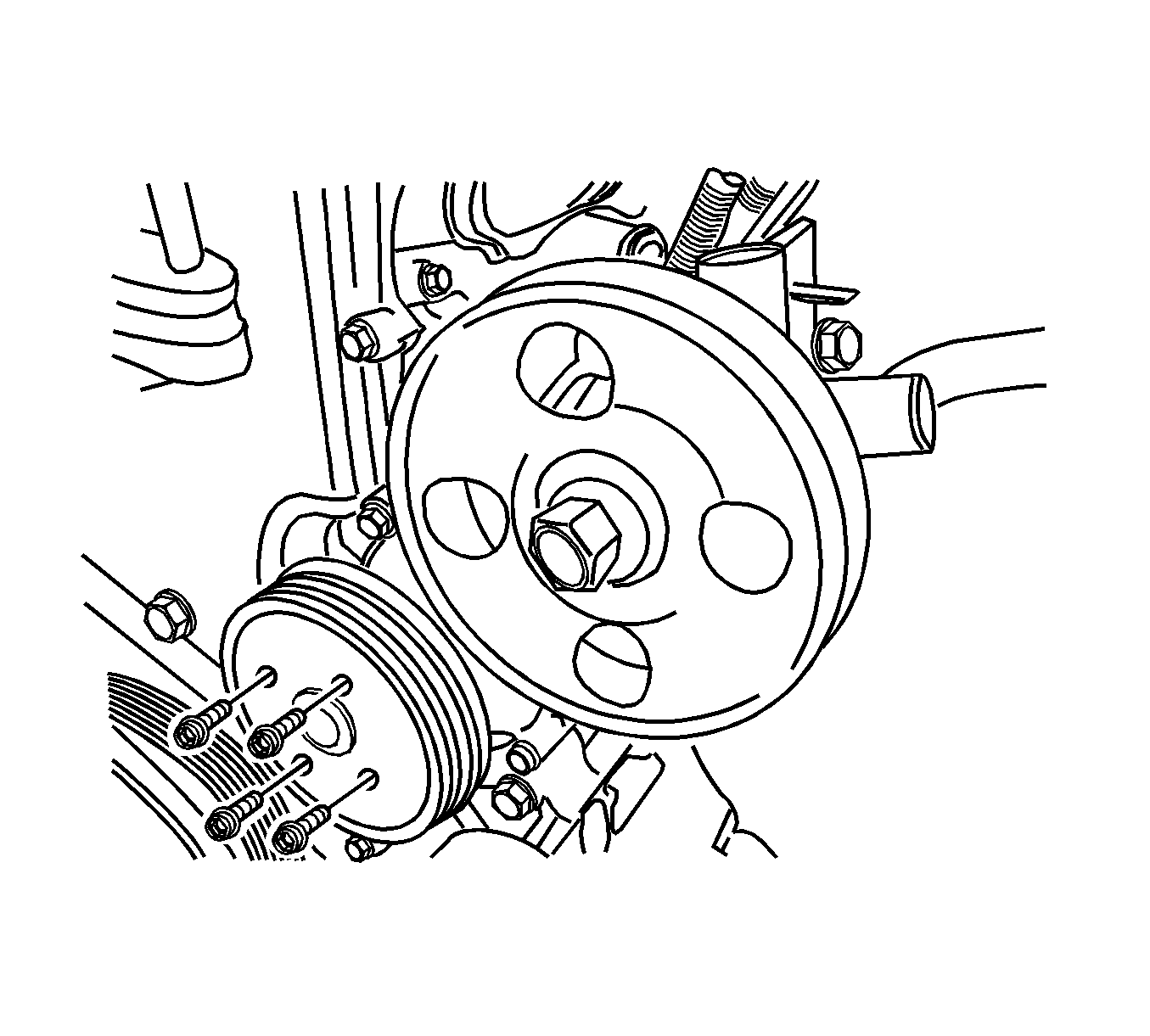
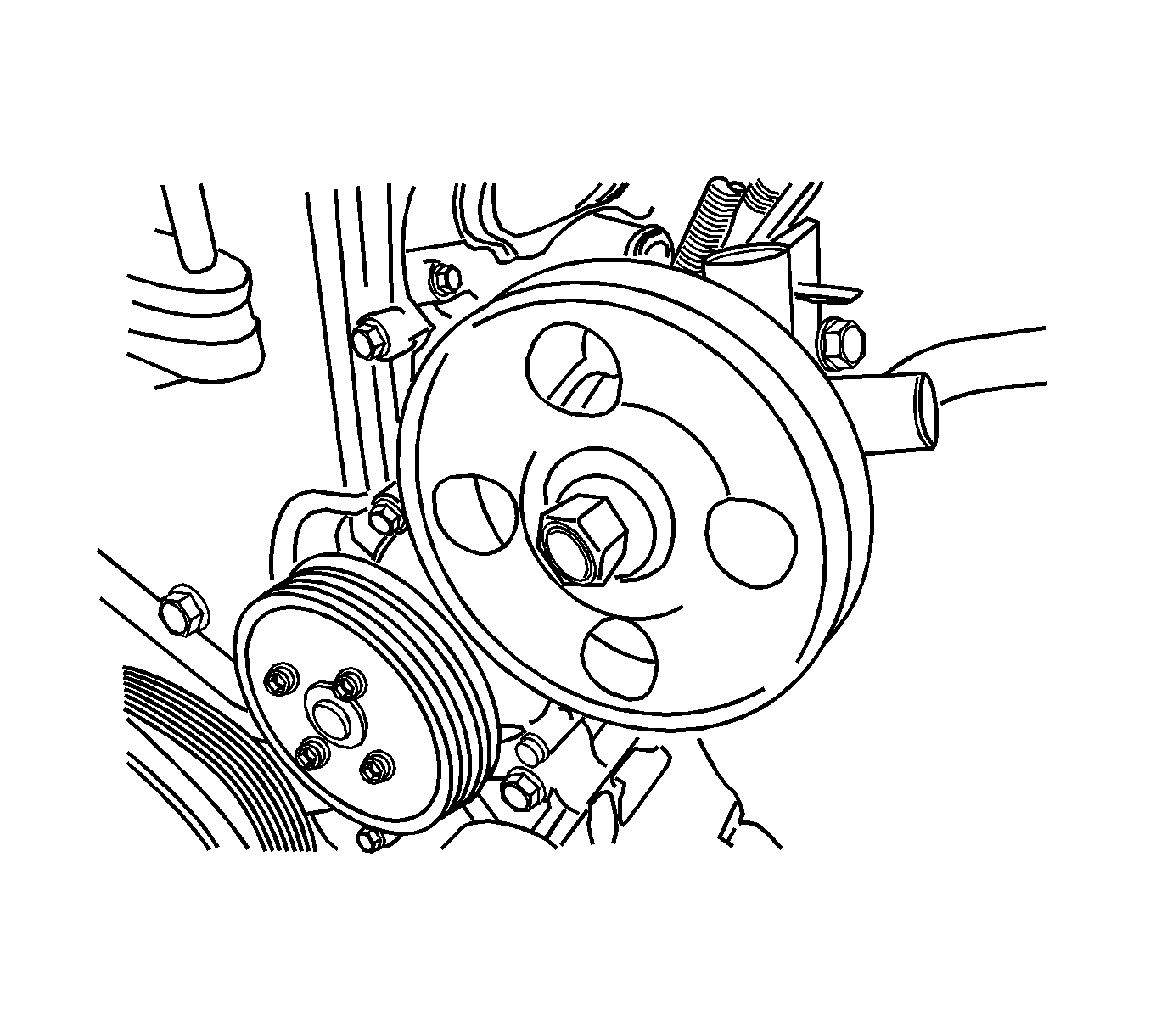
- Remove the water pump pulley.
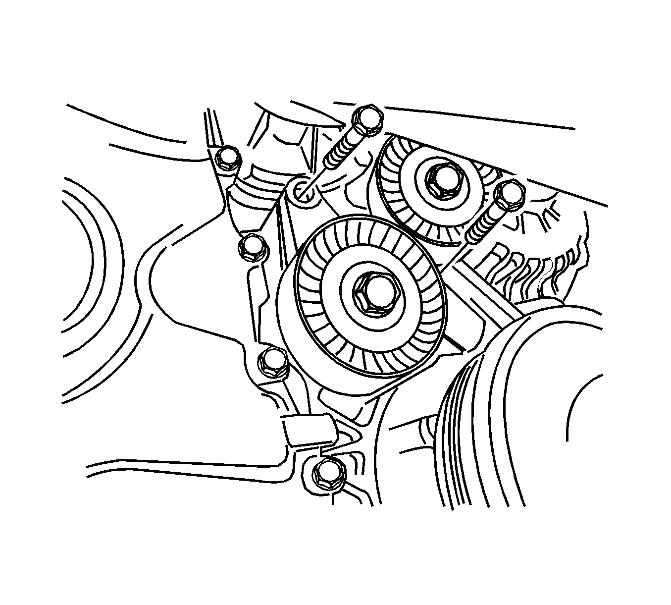
- Remove the drive belt automatic tensioner retaining bolts and the tensioner.
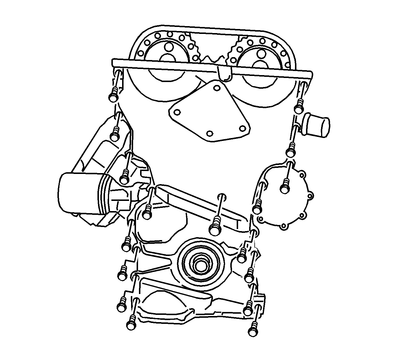
- Remove the timing chain cover.
- Remove 2 dowel rings for timing cover.
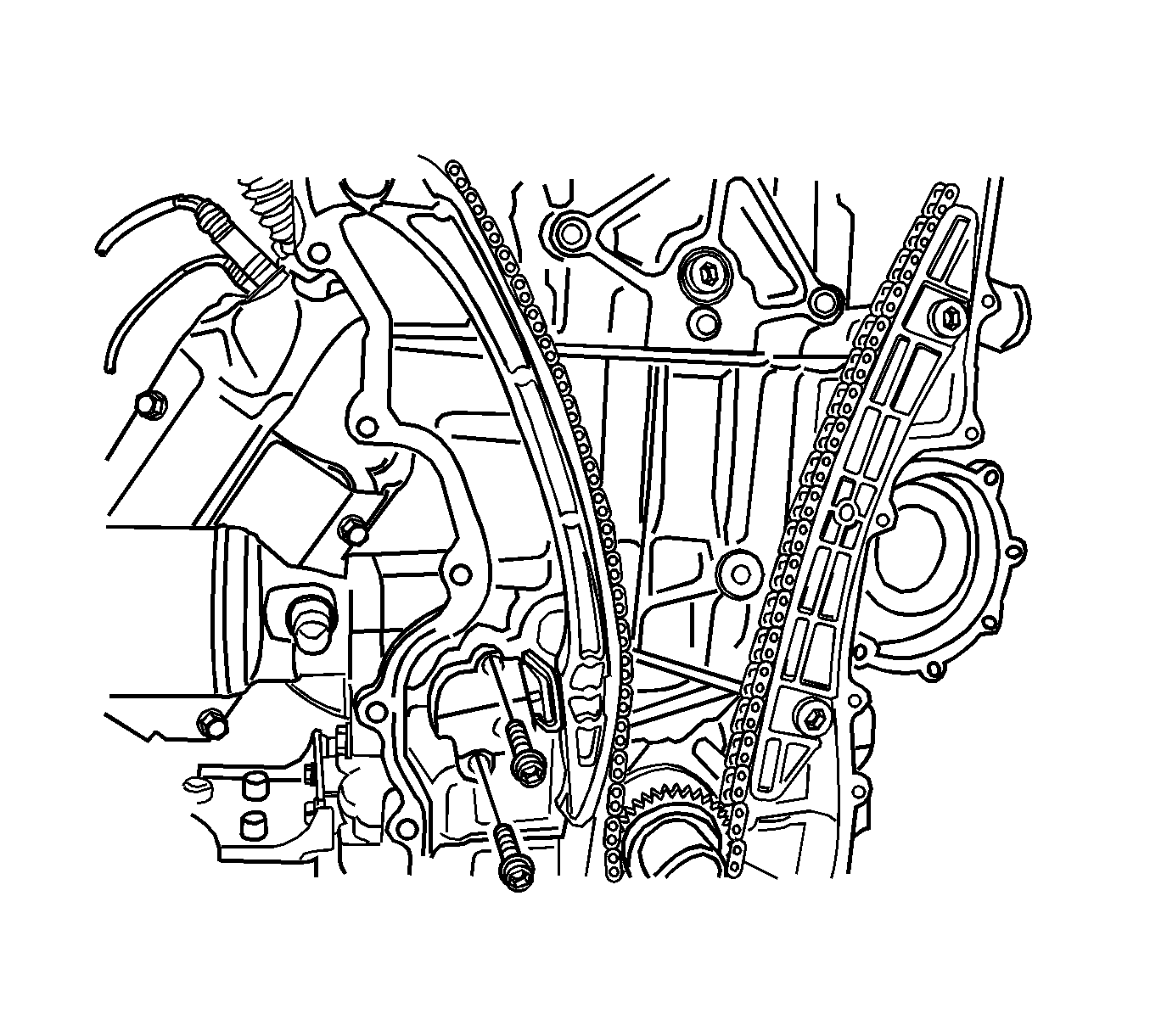
- Remove the timing chain tensioner.
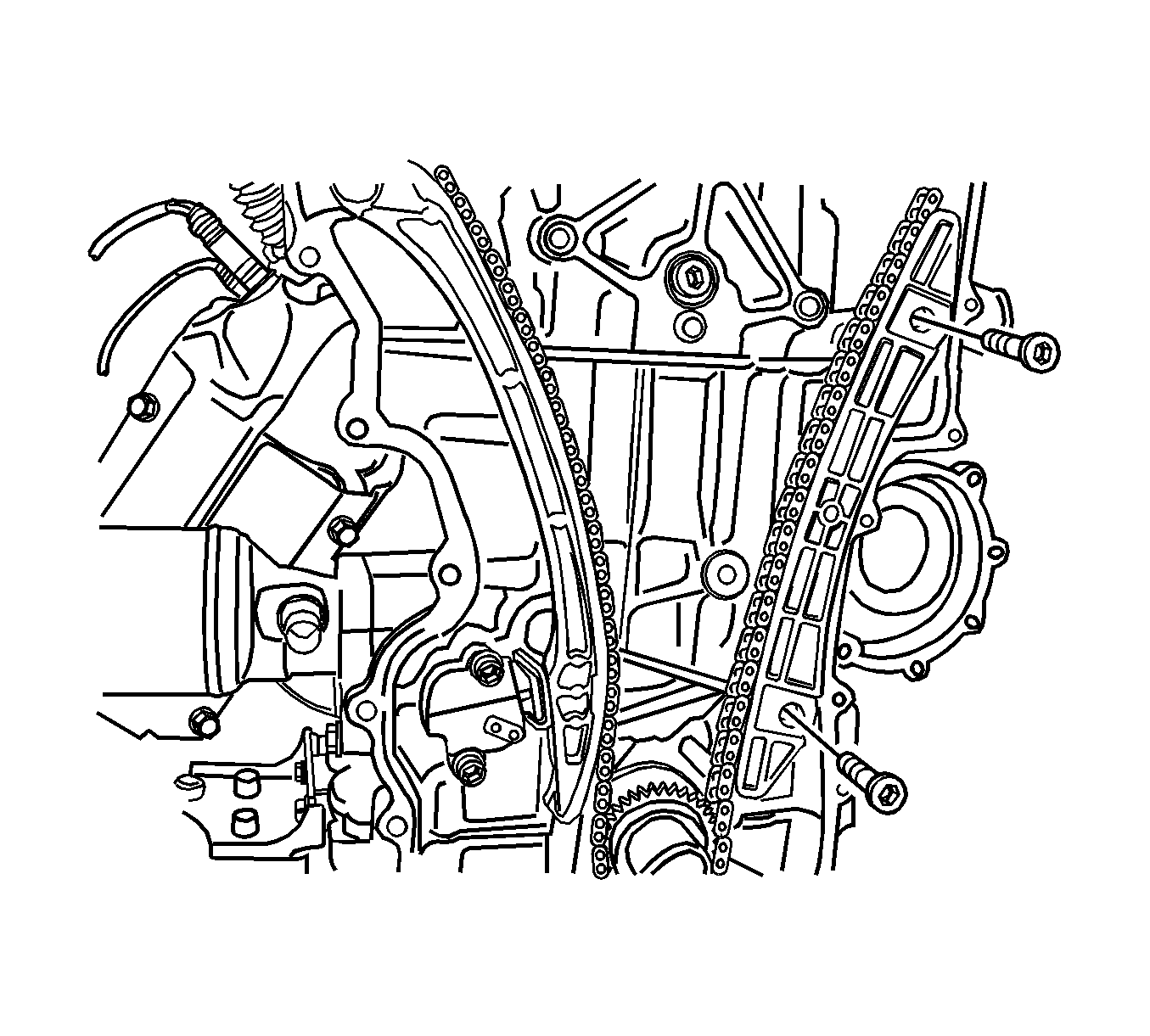
- Remove the fixed timing chain guide.
- Remove the timing chain lever.
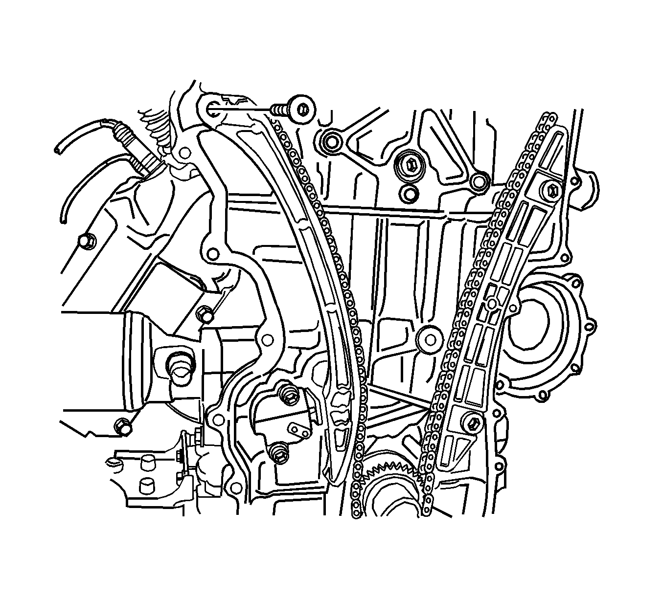
- Remove the top chain guide.
- Remove the timing chain.
- Remove the crankshaft sprocket and the woodruff key.
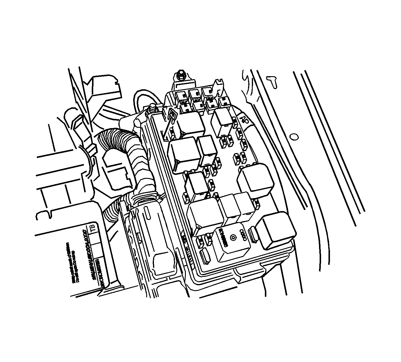
Caution: Refer to Battery Disconnect Caution in the Preface section.
Important: Very high torque is required to remove or to install the crankshaft pulley. Never remove the crankshaft pulley when the vehicle is hung on the lift.
Installation Procedure
- Install the crankshaft sprocket and the woodruff key.
- Install the timing chain after aligning both the mark on the camshaft sprocket and on the timing chain using the EN-47613 (1).
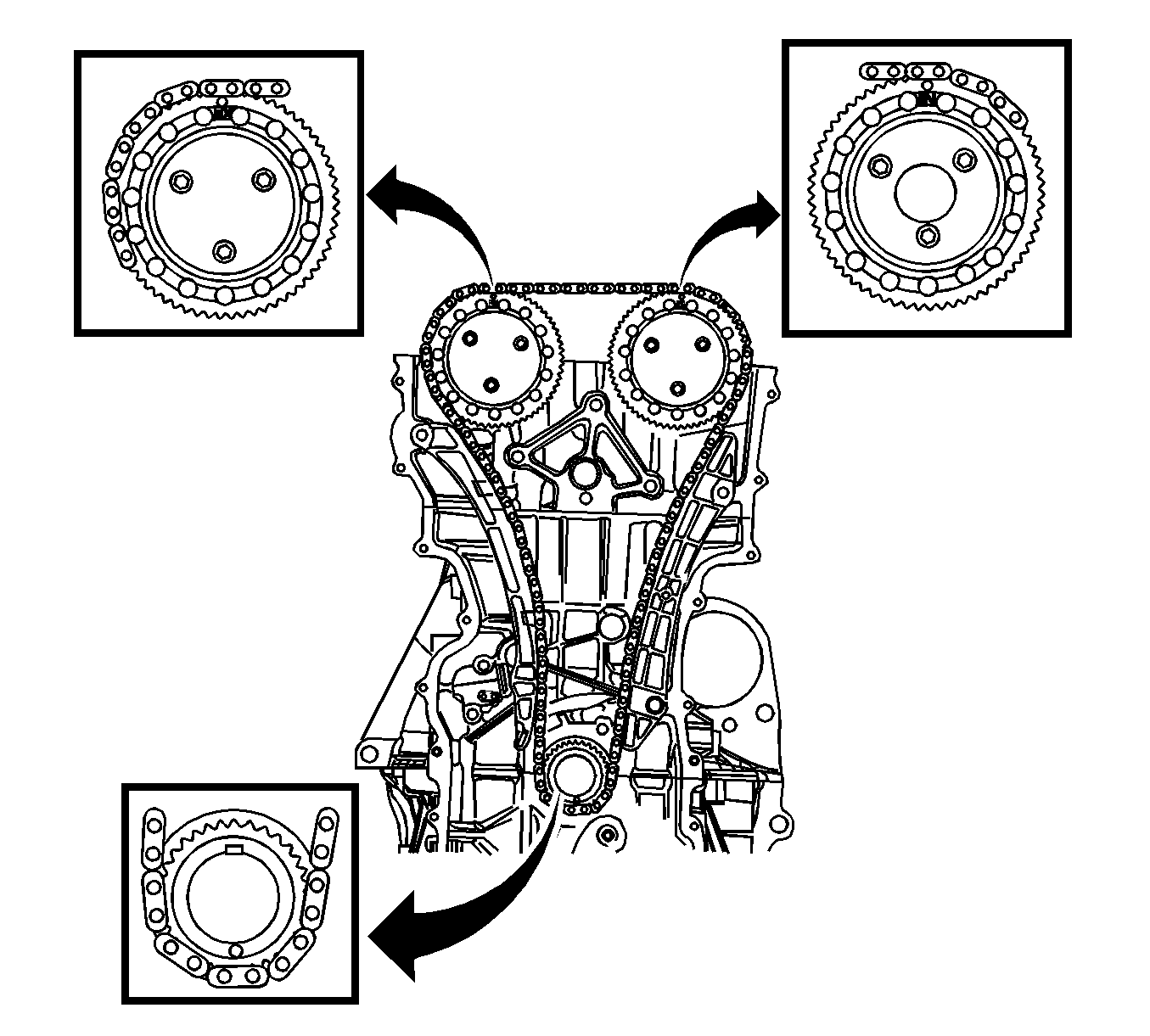
- Align both the timing mark on the crankshaft sprocket and on the timing chain.
- Adjust the crankshaft using the EN-47617 (1).
- Make sure the 3 timing marks on the timing chain are exactly aligned with the marks on the exhaust camshaft sprocket, intake camshaft sprocket, ant crankshaft sprocket respectively.
- Install the fixed timing chain guide.
- Install the timing chain lever.
- Install the timing chain tensioner.
- Install the top chain guide.
- Install 2 dowel rings.
- Apply the liquid gasket Loctite® 5900-M8585 on the timing chain cover.
- Install the EN-47612 (1) and position the timing chain cover.
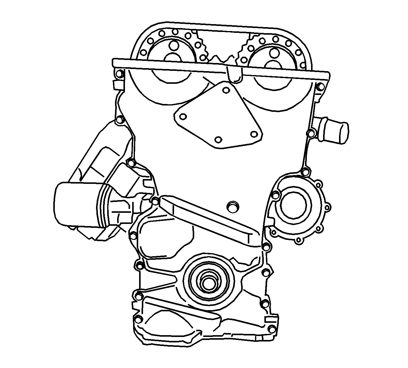
- Install the timing chain cover.
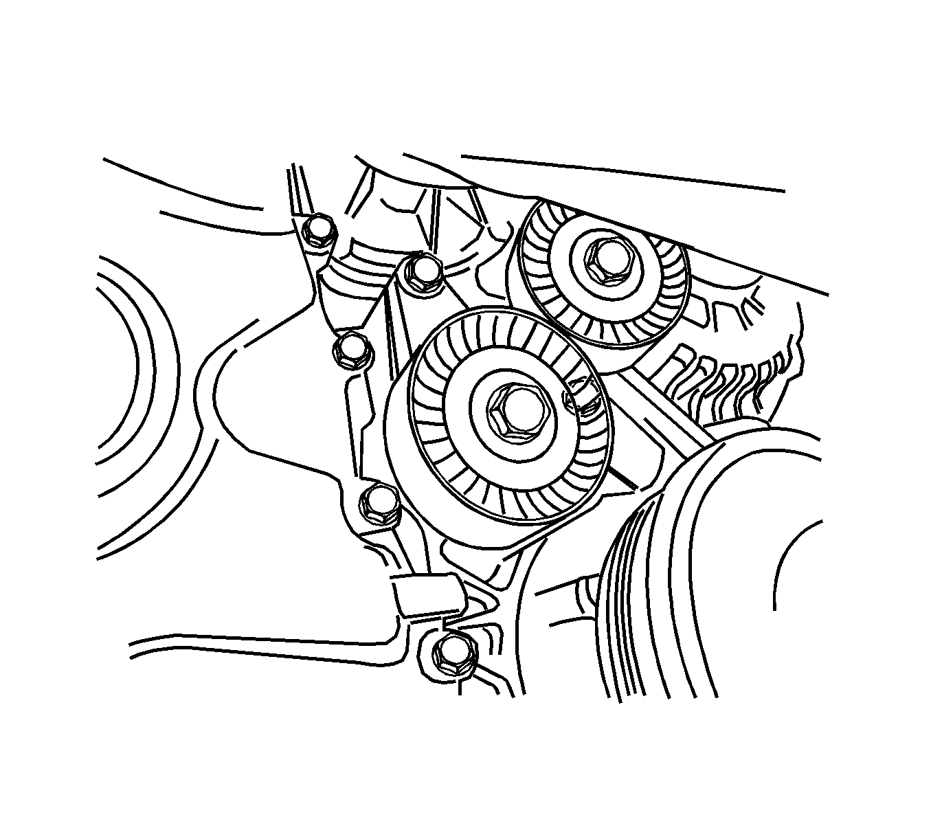
- Install the drive belt automatic tensioner.
- Install the water pump pulley.
- Install the engine mount bracket support.
- Install the crankshaft pulley. Tighten the crankshaft pulley bolt using the EN-47610 (1) and the EN-47611 (2).
- Install the oil pan. Refer to Oil Pan Replacement .
- Install the cylinder head cover. Refer to Cylinder Head Cover Replacement .
- Install the drive belt.
- Install the intake manifold. Refer to Intake Manifold Replacement .
- Install the flexible plate.
- Mount the engine on the J 39580 (1).
- Install the transaxle to the engine assembly.
- Install the engine and transaxle assembly. Refer to Engine Replacement .
- Install the fuel pump fuse.
- Connect the negative battery cable.
- Refill the crankcase with engine oil.
- Refill the engine coolant system. Refer to Cooling System Draining and Filling .
- Fill and bleed the power steering system. Refer to Power Steering System Bleeding .
- Refill the A/C system. Refer to Refrigerant Recovery and Recharging .
Notice: Refer to Fastener Notice in the Preface section.
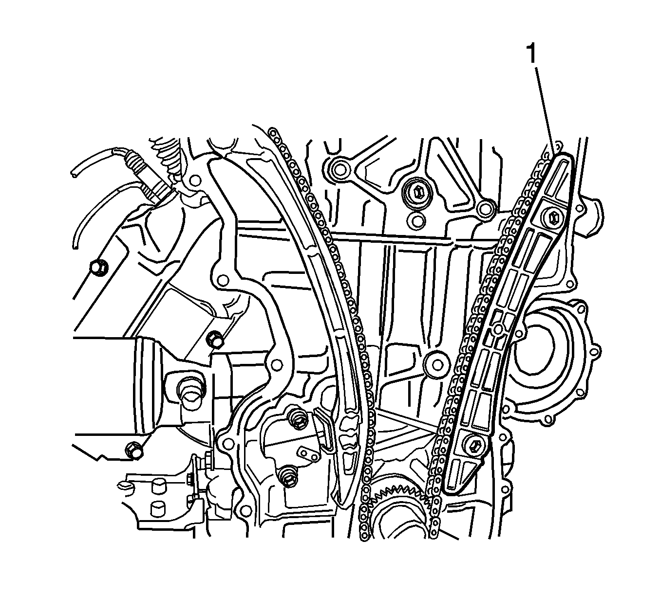
Tighten
Tighten the fixed timing chain guide bolts to 20 N·m (15 lb ft).
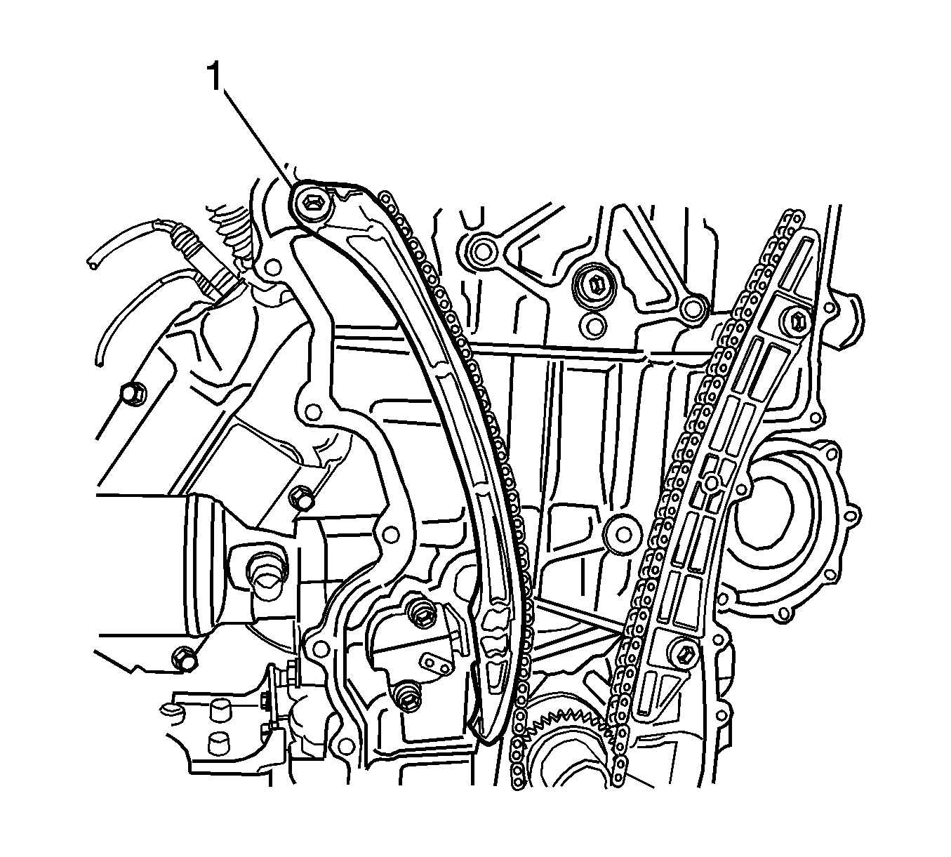
Tighten
Tighten the timing chain lever bolt to 20 N·m (15 lb ft).
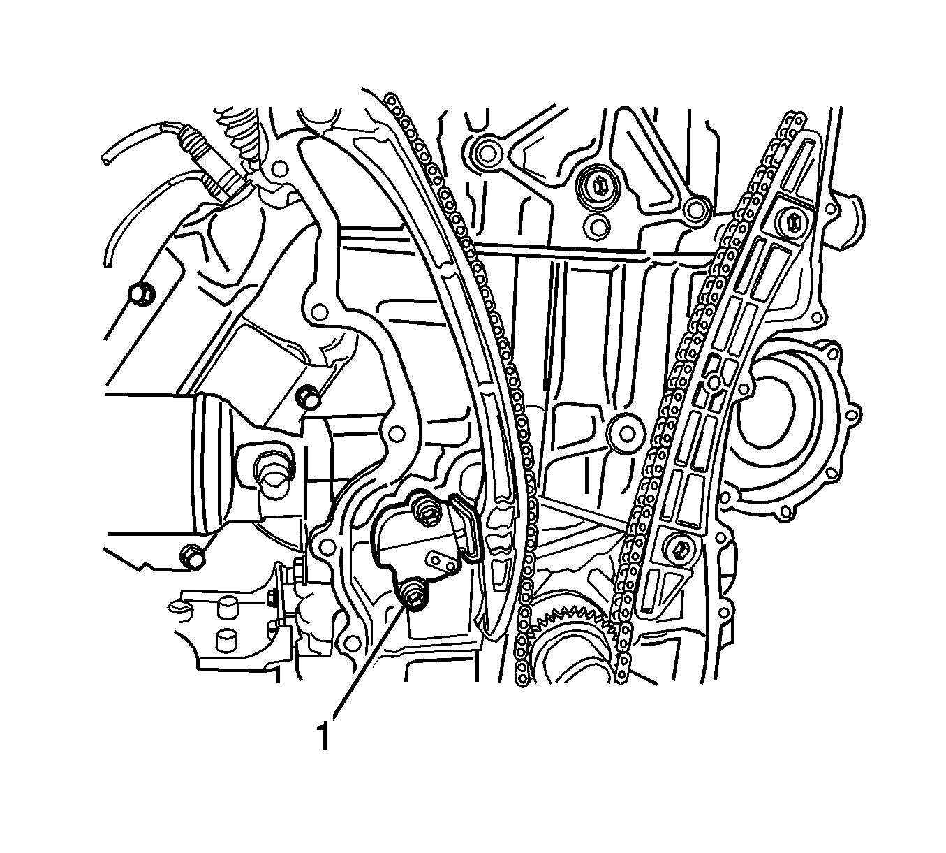
Tighten
Tighten the timing chain tensioner bolt to 20 N·m (15 lb ft).
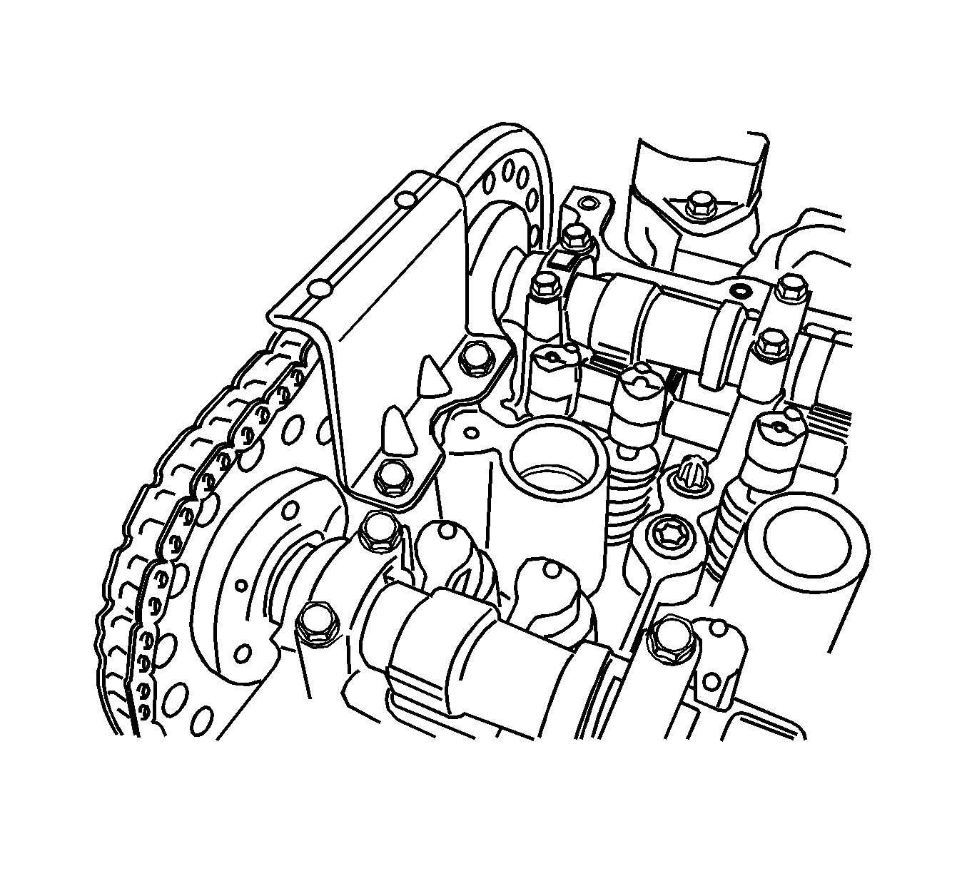
Tighten
Tighten the top chain guide bolt to 10 N·m (89 lb in).
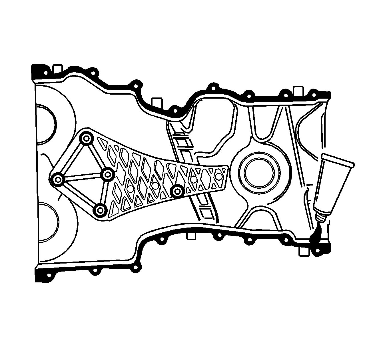
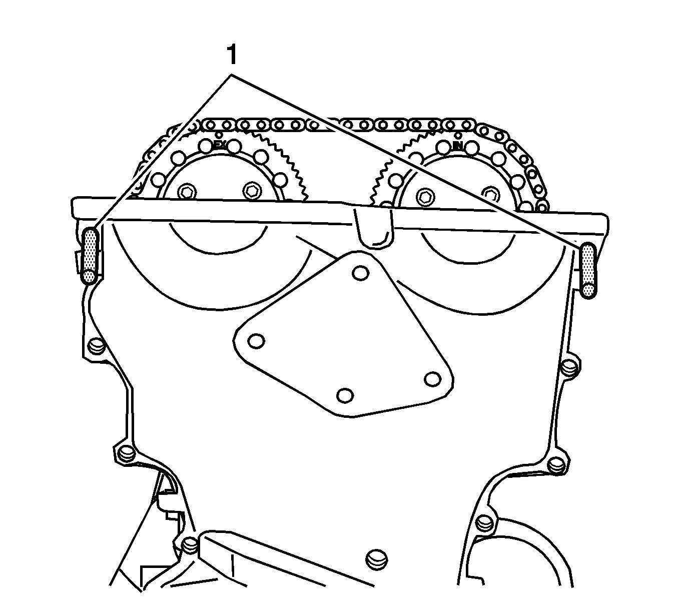
Important: Be sure the applied liquid gasket is not damaged when installing the timing chain cover.
Tighten
| • | Tighten the timing chain cover center bolt to 20 N·m (15 lb ft). |
| • | Tighten the timing chain cover bolts to 8 N·m (71 lb in). |
Tighten
Tighten the drive belt automatic tensioner retaining bolt to 25 N·m (18 lb ft).
Tighten
Tighten the water pump pulley bolts to 10 N·m (89 lb in).
Tighten
Tighten the engine mount bracket support bolts to 28 N·m (21 lb ft).
Tighten
Tighten the crankshaft pulley bolt to 550 N·m (406 lb ft).
Tighten
Tighten the flexible plate bolts to 75 N·m (55 lb ft).

