For 1990-2009 cars only
Removal Procedure
- Disconnect the negative battery cable.
- Remove the engine cover. Refer to Engine Cover Replacement .
- Remove the charge air system hoses and ducts. Refer to Charge Air Cooler Inlet Pipe and Outlet Pipe Replacement .
- Disconnect the radiator lower hose and drain coolant. Refer to Cooling System Draining and Filling .
- Remove the accessory belt. Refer to Drive Belt Replacement .
- Remove the fuel pipe-to-injection pump from the fuel injection pump.
- Remove the power steering pump fastener and pull it left side.
- Remove the coolant hose from intake manifold.
- Remove the radiator upper hose.
- Remove the injection pump return hose.
- Remove the oil level indicator tube.
- Remove the fuel pipe-to-common rail between common rail and fuel injection pump. Refer to Fuel Injector Fuel Feed Pipe Replacement .
- Remove the engine wiring.
- Remove the engine wiring harness guide.
- Remove the coolant by-pass hose.
- Remove the EGR cooler outlet pipe.
- Remove the intake manifold with the gasket.
Caution: Refer to Battery Disconnect Caution in the Preface section.
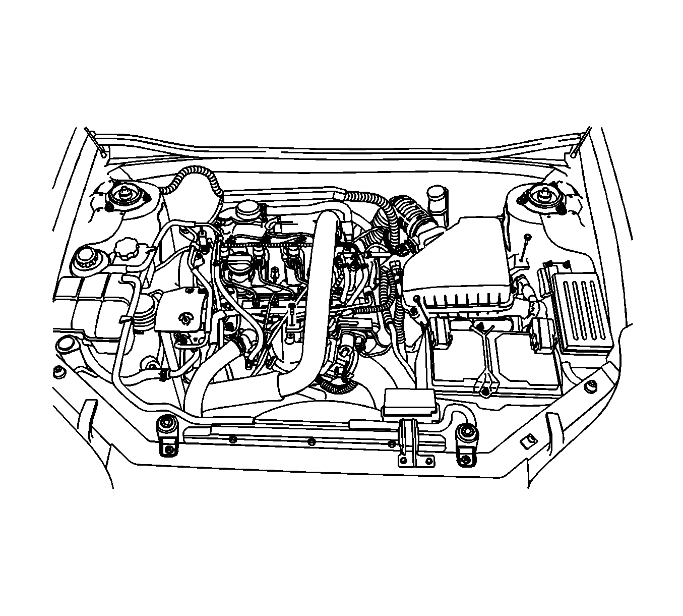
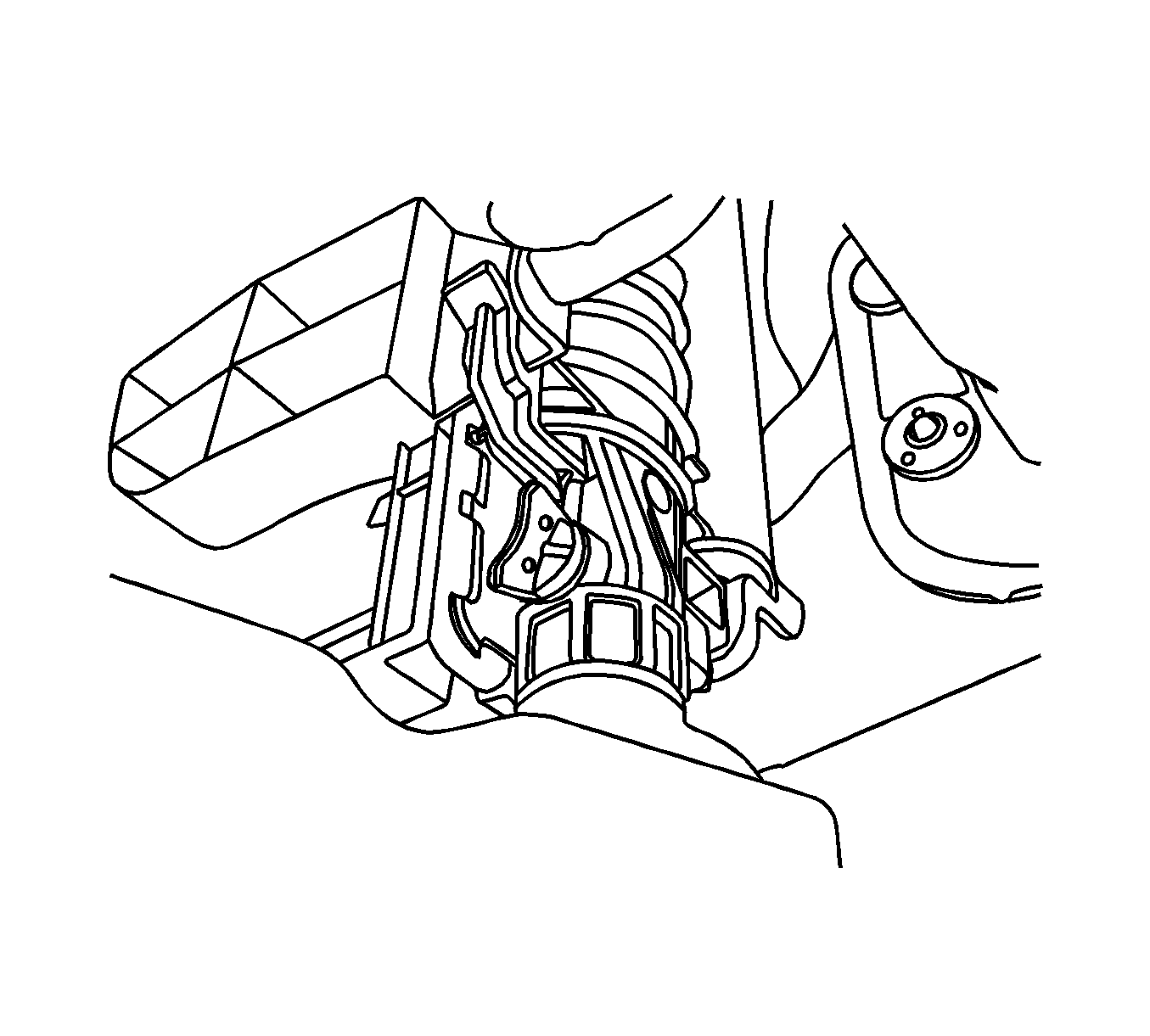
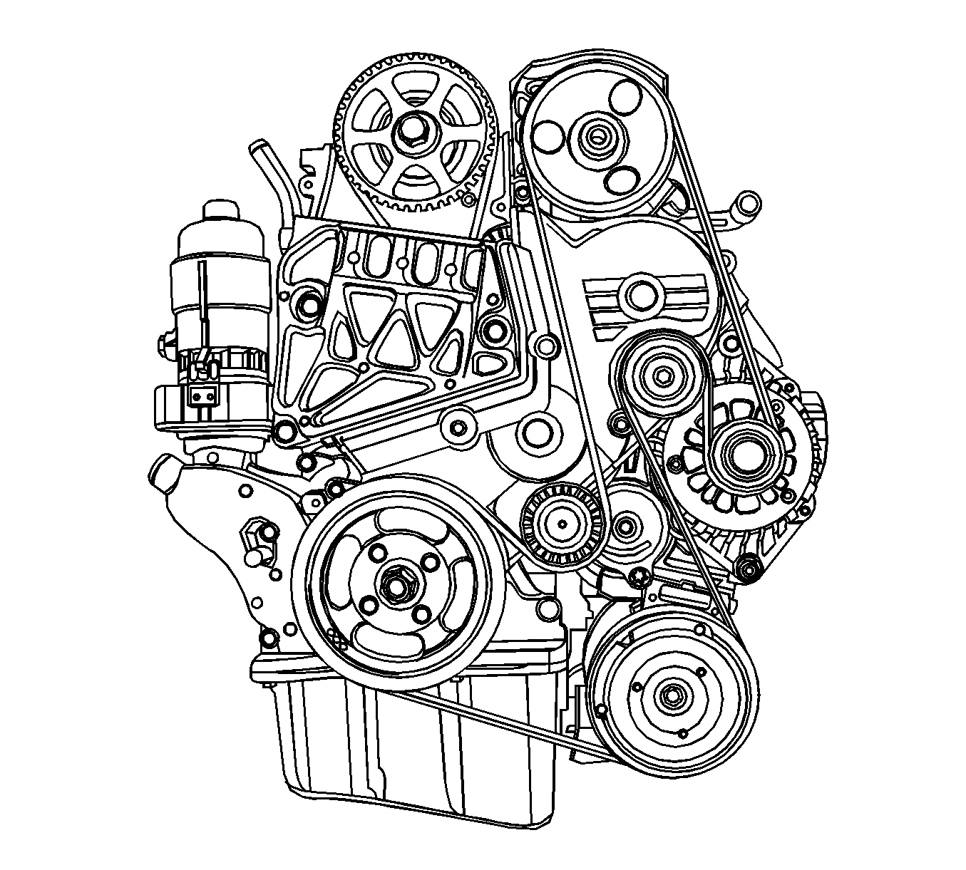
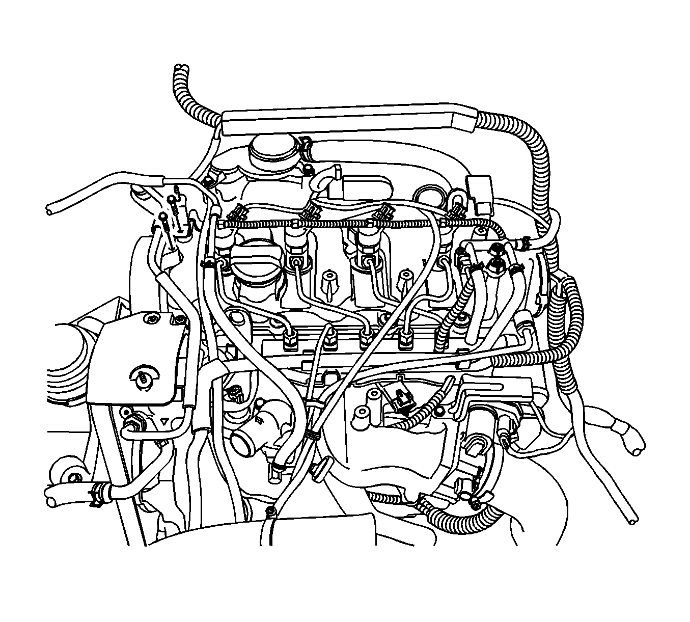
| 13.1. | Disconnect the common rail pressure sensor connector. |
| 13.2. | Disconnect the CTS connector. |
| 13.3. | Disconnect the injection pump connector. |
| 13.4. | Disconnect the generator connector. |
| 13.5. | Disconnect the A/C compressor connector. |
| 13.6. | Disconnect the starter solenoid wire connector. |
| 13.7. | Disconnect the T-MAP sensor connector |
| 13.8. | Disconnect the CMP sensor connector. |
| 13.9. | Disconnect the ETC body connector. |
| 13.10. | Disconnect the common rail regulator connector. |
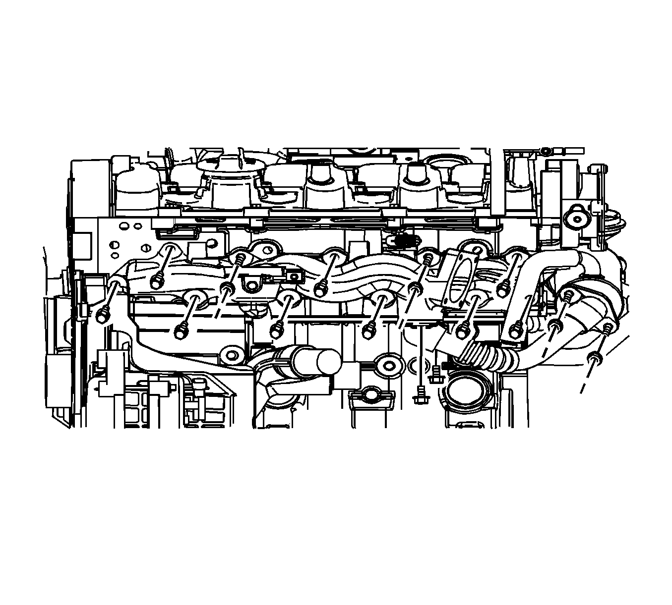
Installation Procedure
- Install the intake manifold with a new gasket.
- Install the EGR cooler outlet pipe.
- Install the engine wiring.
- Install the fuel pipe-to-common rail between common rail and fuel injection pump. Refer to Fuel Injector Fuel Feed Pipe Replacement .
- Install the oil level indicator tube.
- Install the power steering pump.
- Install the fuel pipe-to-injection pump to the fuel injection pump.

Notice: Refer to Fastener Notice in the Preface section.
Tighten
| • | Tighten the intake manifold bolts and nuts 23 N·m (17 lb ft). |
| • | Tighten the EGR cooler outlet pipe bolts and nuts 20 N·m (14.8 lb ft). |

Tighten
| • | Tighten the glow plug fuse box bolts to 10 N·m (88.5 lb in). |
| • | Tighten the engine wiring splice pack tightening bolt to 15 N·m (11.1 lb ft). |
| • | Tighten the fuel pipe-to-common rail to 20 N·m (14.8 lb ft). |
| • | Tighten the fuel pipe-to-common rail retaining bolt to 10 N·m (88.5 lb in). |
| • | Tighten the oil level indicator tube bolts to 11 N·m (97.4 lb in). |
| • | Tighten the power steering pump bolts to 25 N·m (18.4 lb ft). |
| • | Tighten the fuel pipe-to-injection pump retaining bolt (to intake manifold) to 9 N·m (79.7 lb in). |
| • | Tighten the fuel pipe-to-injection pump retaining bolt to 25 N·m (18.4 lb ft). |
