For 1990-2009 cars only
Special Tools
| • | J 28647-B Engine Support Fixture |
| • | KM-6625 Flywheel Locking Device |
| • | KM-6333 Fixing Rod |
| • | MK-6628 Locking Tool |
| • | MK-6340 Locking Tool |
Removal Procedure
- Disconnect the battery negative cable. Refer to Battery Negative Cable Disconnection and Connection.
- Remove the air cleaner assembly. Refer to Air Cleaner Assembly Replacement.
- Install J 28647-B Engine Support Fixture .
- Remove the accessory belt. Refer to Drive Belt Replacement.
- Remove the accessory belt tensioner. Refer to Drive Belt Tensioner Replacement.
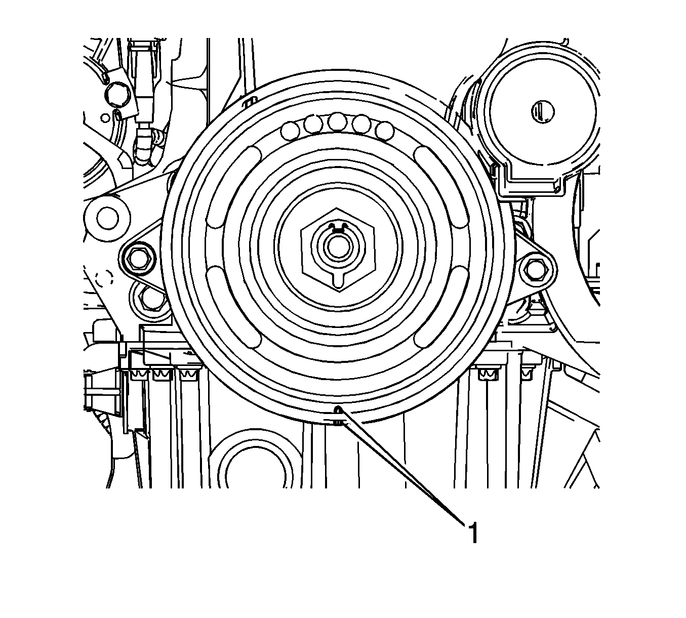
- Rotate the crankshaft pulley clockwise.
- Align the notches (1) between the pulley and the cover.
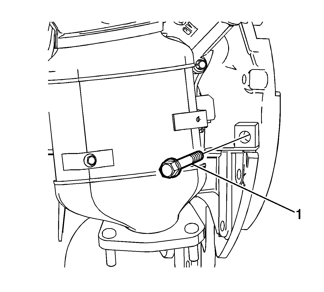
- Remove the transmission bolt (1).
- Install KM-6625 locking device to block the crankshaft.
- Install the transmission bolt (1).
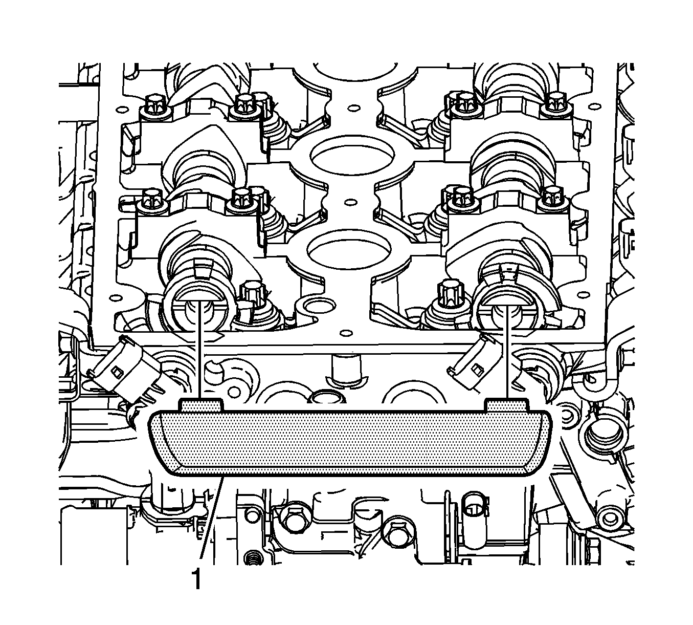
- Remove the cylinder head cover. Refer to Valve Rocker Arm Cover Replacement.
- Remove the engine mount. Refer to Engine Mount Replacement.
- Remove the crankshaft pulley (2).
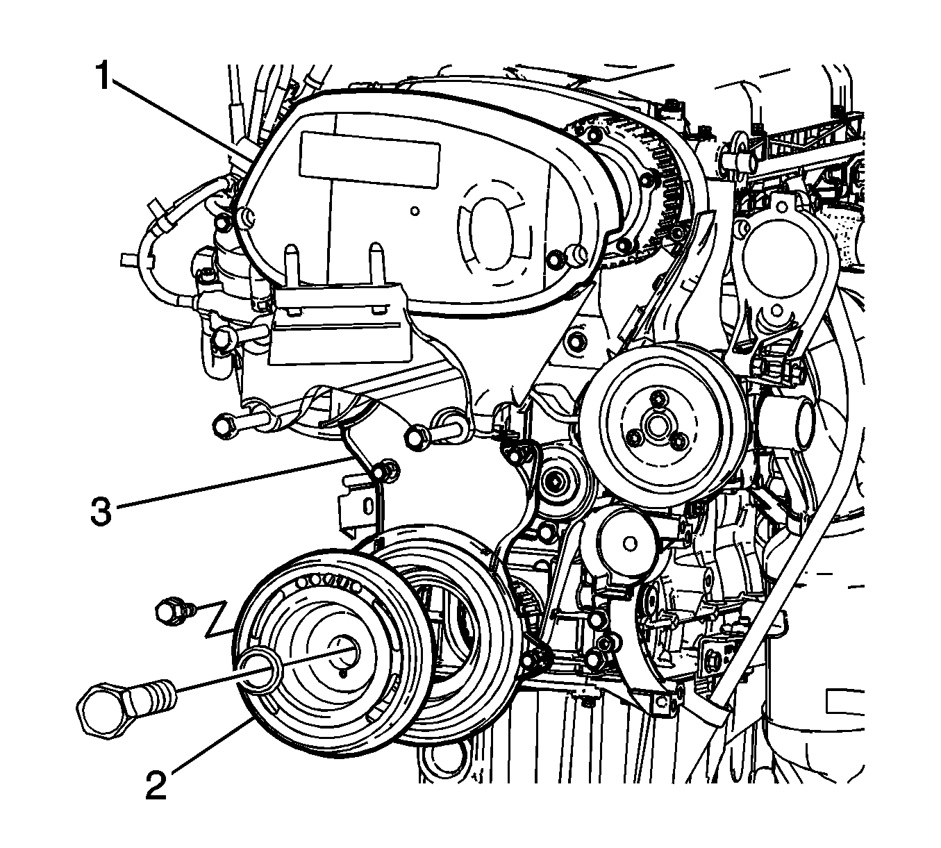
- Remove the timing belt upper cover (1).
- Remove the engine mount bracket.
- Remove the timing belt lower cover (3).
- Remove the timing belt center cover.
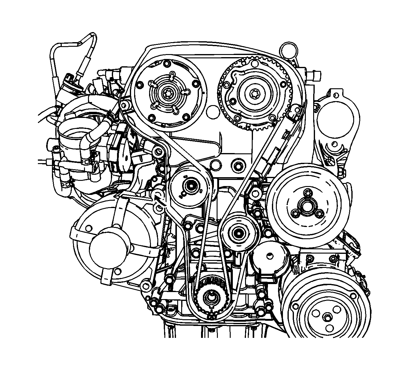
- Install KM-6333 rod during rotating the timing belt tensioner.
- Remove the timing belt.
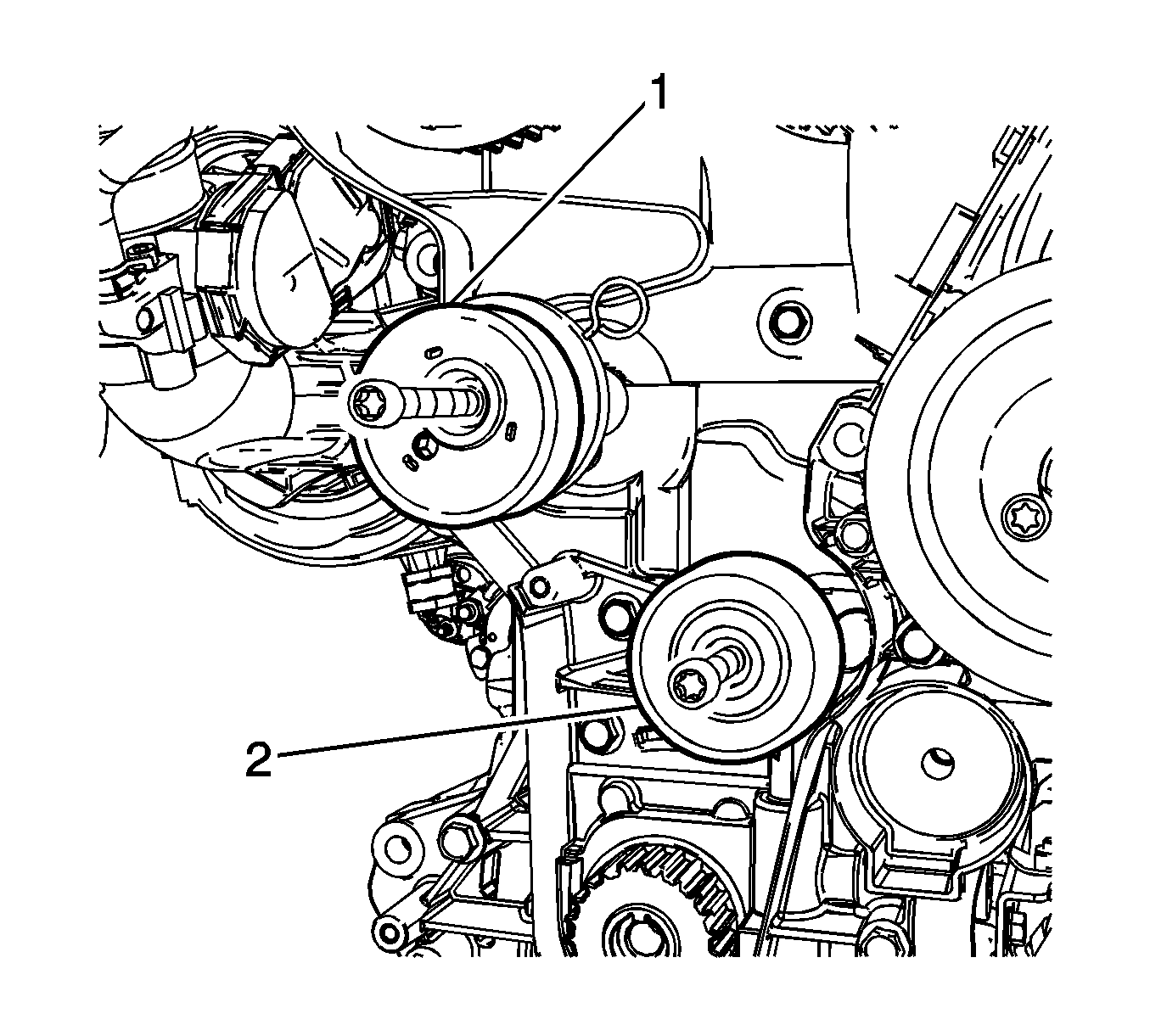
- Remove the timing belt tensioner (1).
- Remove the timing belt idler (2).
Warning: Refer to Battery Disconnect Warning in the Preface section.
Adjustment Procedure
- Align the both camshaft horizontally to install the MK-6628 locking tool .
- Confirm the both camshaft sprocket spot aligned.
- Prepare the right half of MK-6340 locking tool .
- Unscrew the bolts (1) and detach the front panel (2) from MK-6628 locking tool .
- Confirm aligning between the intake side spot (3) and the exhaust side spot (4) on the camshaft sprockets.
- If not aligned as shown, remove and install the camshaft sprocket to align.
- Insert the left of MK-6340 (1) into the intake camshaft sprocket side.
- Insert the right of MK-6340 (2) into the exhaust camshaft sprocket side.
- Confirm alignment of the notches between the crankshaft sprocket and the cover.
- Install the timing belt idler (2) and tighten to 50 N·m (36.8 lb ft).
- Install the timing belt tensioner (1) and tighten to 55 N·m (40.6 lb ft).
- Install the timing belt and adjust.
- Pull out KM-6333 fixing rod .
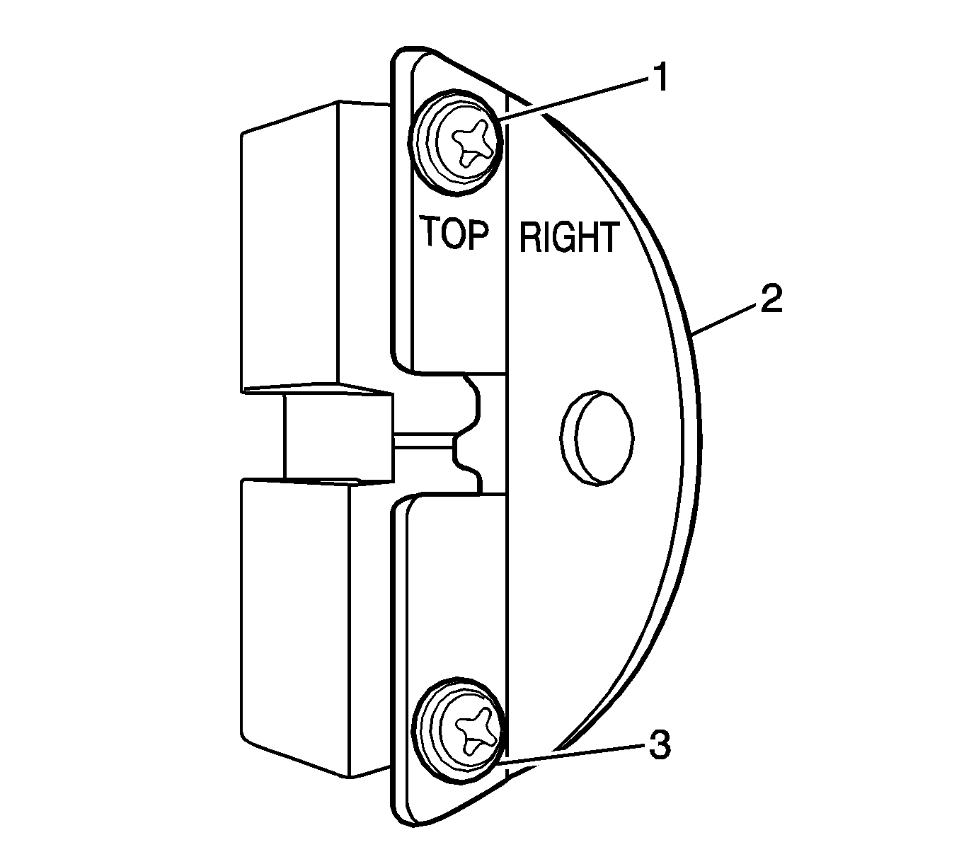
Note: Recognizable from the lettering "Right"
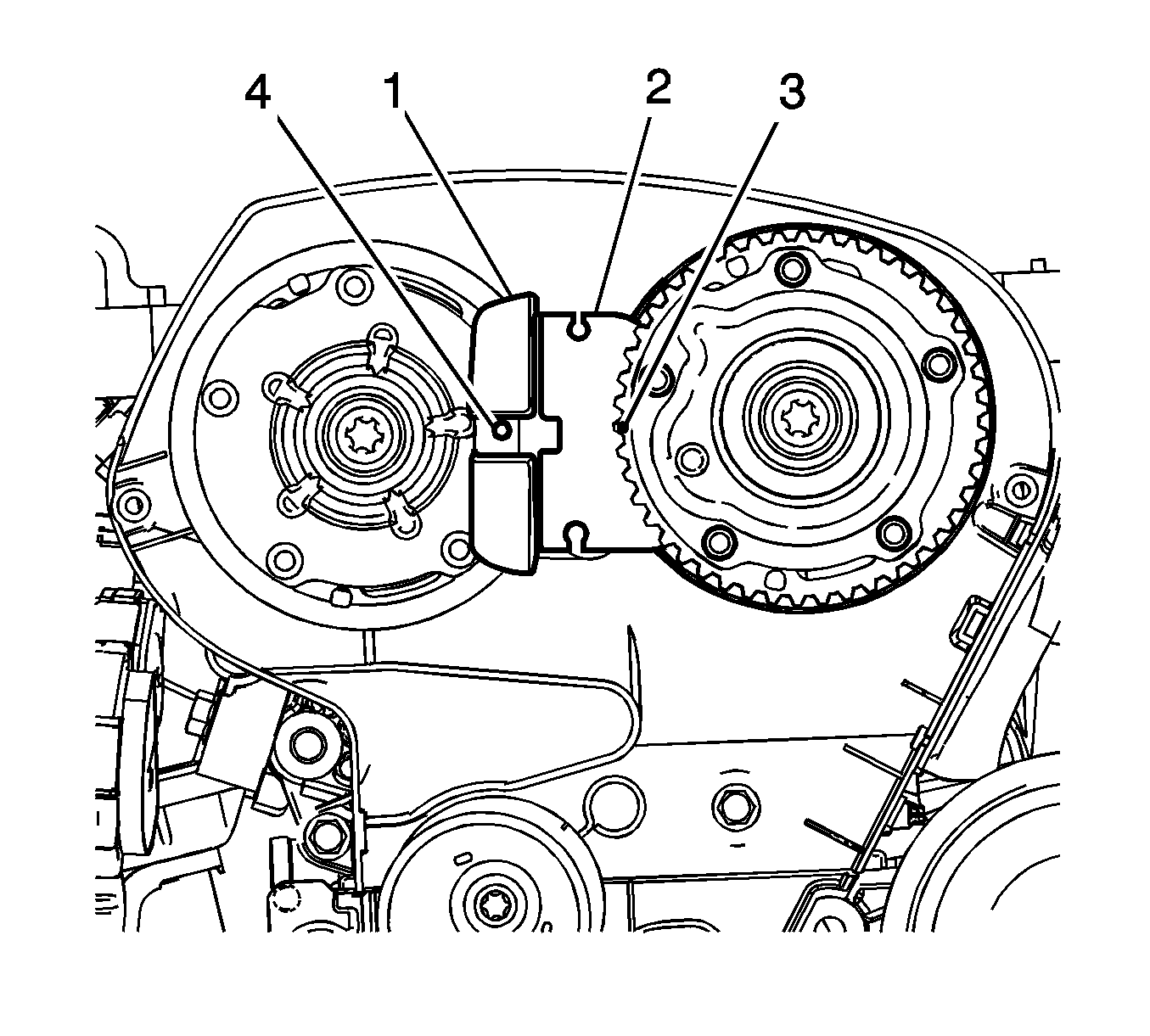
Note: The spot-type marking (4) on the intake camshaft sprocket does not correspond to the groove of MK-6628 locking tool during this process.
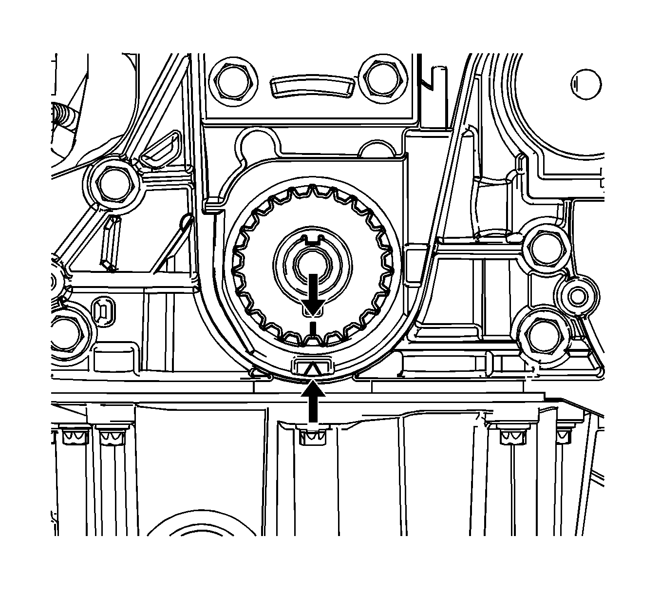
Note: If not aligned the notches, rotate the crankshaft until aligning after remove KM-6625 .
Caution: Refer to Fastener Caution in the Preface section.
Installation Procedure
- Install the timing belt center cover.
- Install the timing belt lower cover (3) and tighten the bolts to 6 N·m (53.1 lb in).
- Install the engine mount bracket and tighten the bolt to 65 N·m (47.9 lb ft).
- Install the timing belt upper cover (1) and tighten the bolts to 4 N·m (35.4 lb ft).
- Install the crankshaft pulley (2) with aligning crankshaft pulley notches and tighten to 25 N·m (18.4 lb ft).
- Install the engine mount. Refer to Engine Mount Replacement
- Install the cylinder head cover. Refer to Engine Mount Replacement.
- Install the accessory belt. Refer to Drive Belt Tensioner Replacement.
- Install the accessory belt tensioner. Refer to Drive Belt Replacement.
- Remove the transmission bolt (1).
- Remove KM-6625 locking device to block the crankshaft.
- Install the transmission bolt (1) and tighten to 60 N·m (44.2 lb ft).
- Remove J 28647-B Engine Support Fixture .
- Install the air cleaner assembly. Refer to Air Cleaner Assembly Replacement.
- Connect the battery negative cable. Refer to Battery Negative Cable Disconnection and Connection.
Caution: Refer to Fastener Caution in the Preface section.
