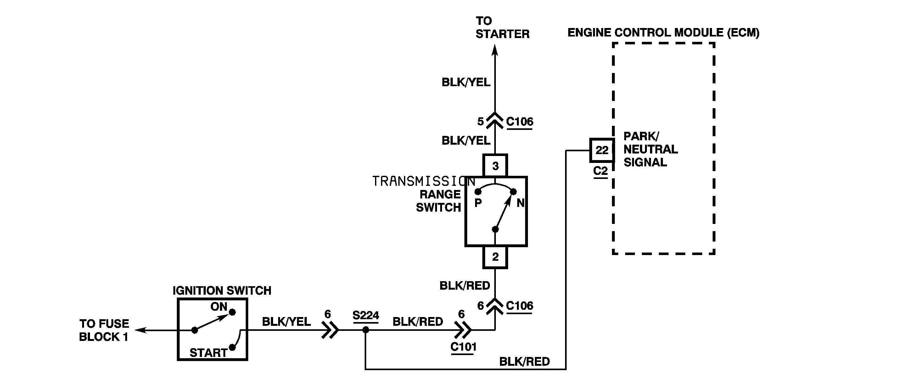
Circuit Description
The engine control module (ECM) determines when the vehicle is in Park "P" or Neutral "N" gear position through the transmission range switch. The BLK/RED wire to the ECM is grounded by the transmission range switch when the transmission manual selector is in either Park "P" or Neutral "N" gear position.
DTC Detecting Condition
| • | Engine speed changed from below 300 rpm to over 500 rpm when vehicle speed is 0 km/h (0 mph) and the transmission range switch is "open" (R, D, 2 or L gear positions). |
| • | Transmission range switch "closed" (P or N gear position) is detected for 10 seconds while engine is running at over 2,000 rpm and with more than 48.6% calculated load value. |
Action Taken When the DTC Sets
| • | DTC P1715 is stored. |
| • | The OD/OFF indicator turns ON. |
| • | The malfunction indicator lamp (MIL) turns ON. |
Diagnostic Aids
An intermittent condition may be caused by a poor connection, rubbed through wire insulation or a wire broken inside the insulation. Inspect the ECM and TCM harness connectors for backed out terminals, improper mating, broken locks, improperly formed or damaged terminals and for poor terminal-to-wire connections.
Test Description
The numbers below refer to the step numbers on the diagnostic table.
-
Checks for operation of the transmission range switch.
-
Checks for an open in the BLK/RED wire.
-
Checks that the transmission range switch opens when the manual selector is not in either Park or Neutral gear positions.
-
Determines whether the transmission range switch stays closed at all times or BLK/RED wire is shorted to ground.
-
Checks for an open in the BLK/RED wire.
Step | Action | Value(s) | Yes | No |
|---|---|---|---|---|
1 | Was the On-Board Diagnostic (OBD) System Check performed? | -- | ||
Does the engine crank? | -- | Perform System Diagnosis Starter System in Engine Electrical | ||
Is the voltage at or less than the value specified? | 1 V | |||
Is the voltage within the specified values on each of the gear positions mentioned above? | 10-14 V | |||
Is the voltage within the specified values? | 10-14 V | |||
Is the resistance within the specified value? | ∞ | |||
7 |
Can continuity be obtained? | -- | ||
8 |
Is the action complete? | -- | -- | |
9 |
Does this DTC reset? | -- | ||
10 | Inspect the BLK/RED wire and connectors between the ECM and the transmission range switch for damage which may result in an open circuit or short to ground with all the connectors connected. Repair damage, if evident. Is the action complete? | -- | -- | |
11 | Repair the open or high resistance in the BLK/RED wire between S224 and the ECM connector C2 terminal 22. Is the action complete? | -- | -- | |
12 | Repair the short to ground in the BLK/RED wire between the ECM connector C2 terminal 22 and the transmission range switch conductor terminal 2. Is the action complete? | -- | -- | |
13 | Replace the transmission range switch. Refer to Transmission Range Switch Replacement . Does the DTC reset? | -- | -- | |
14 | Replace the ECM. Refer to Engine Control Module Replacement in Engine Controls. Is the action complete? | -- | -- | |
15 |
Does the scan tool display any DTCs? | -- | Go to the applicable DTC table | -- |
