SERVICE MANUAL UPDATE SEC.9J-A REPLACE PGS. FOR SIR DTC 24

Subject: REPLACE PAGES FOR SIR DTC 24
Model and Year: 1992-93GEOMETROCONVERTIBLE 1990-93 GEO STORM
Application: 1992-93 Geo Metro Convertible Model 1990-93 Geo Storm
The supplemental inflatable restraint (SIR) system diagnostic trouble code (DTC) 24 has been updated for the 1992-93 Geo Metro Convertible and the 1990-1993 Geo Storm models. Metro DTC 24 (Page 3 of 4) chart in the 1992-93 Geo Metro Service Manuals (ST370-92 and ST370-93). Storm DTC 24 (Page 4 of 5), contained within this bulletin, replaces the DTC 24 (Page 4 of 5) chart in the 1990-91 Geo Storm Service Manual Supplement Covering the SIR System (ST371-90/91SUPP) as well as the 1992-93 Geo Storm Service Manuals (ST371-92 and ST371-93). Please refer to these replacement pages whenever diagnosing a Metro or Storm SIR system DTC 24.
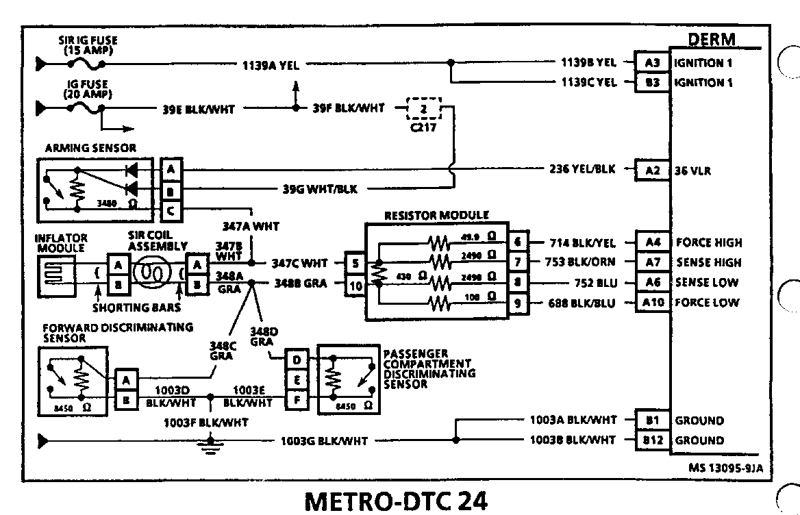
METRO-DTC 24 STEERING COLUMN CIRCUIT VOLTAGE TOO LOW --------------------------------------- Circuit Description:
DTC 24 is set when the voltage at the 'Sense Low' input, terminal 'A6", is within a specific range of "36 VLR" output voltage for 500 milliseconds during the "Continuous Monitoring Tests" performed by the DERM. The 'Continuous Monitoring Tests' are performed by the DERM after the initial "Turn-ON Tests" are completed and are performed every 100 milliseconds while "Ignition 1" voltage is present at the DERM. The 'Continuous Monitoring Tests' check the continuity of the deployment loop from the '36 VLR' output of the DERM through the arming sensor, inflator module and the discriminating sensors to ground. DTC 24 will set if the arming sensor resistance is too high or open, a discriminating sensor is shorted or resistance is too low, the 'Force High,' 'Sense Low' or 'Force Low" circuit is shorted to ground or system voltage, or the "Sense High" circuit is shorted to ground.
Test Conditions:
Tested every 100 milliseconds during the "Continuous Monitoring Tests."
Failure Conditions:
DTC 24 will set if the voltage at the "Sense Low" input, terminal "A6", is within a specific range of -36 VLR" output voltage for 500 milliseconds.
Action Taken: The DERM illuminates the 'INFLREST' indicator.
Conditions to Clear: DTC 24 will clear if the voltage at the "Sense Low" input, terminal 'A6', is within a specific range of -36 VLR- output voltage for 500 milliseconds.
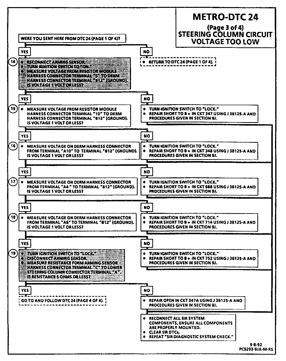
Test Description: Number(s) below refer to circled number(s) on the diagnostic chart.
14. This test checks for a short to B + in CKT 347. 15. This test checks for a short to B + in CKT 348. 16. This test checks for a short to B + in the 'Force Low' CKT 688. 17. This test checks for a short to B + in the "Force High" CKT 714. 18. This test checks for a short to B + in the "Sense Low" CKT 752. 19. This test checks for an open in CKT 347A.
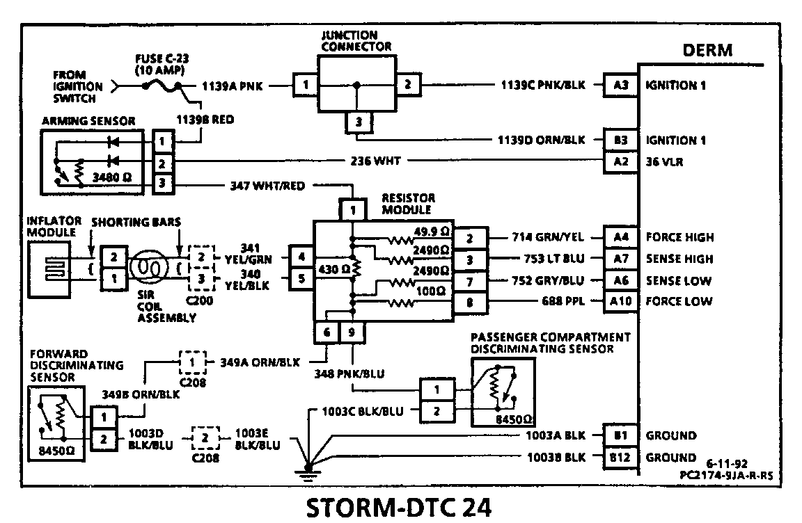
STORM-DTC 24 STEERING COLUMN CIRCUIT VOLTAGE TOO LOW --------------------------------------- Circuit Description:
DTC 24 is set when the voltage at the 'Sense Low' input, terminal 'A6", is within a specific range of "36 VLR" output voltage for 500 milliseconds during the "Continuous Monitoring Tests" performed by the DERM. The 'Continuous Monitoring Tests' are performed by the DERM after the initial "Turn-ON Tests" are completed and are performed every 100 milliseconds while "Ignition 1" voltage is present at the DERM. The 'Continuous Monitoring Tests' check the continuity of the deployment loop from the '36 VLR' output of the DERM through the arming sensor, inflator module and the discriminating sensors to ground. DTC 24 will set if the arming sensor resistance is too high or open, a discriminating sensor is shorted or resistance is too low, the 'Force High,' 'Sense Low' or 'Force Low" circuit is shorted to ground or system voltage, or the "Sense High" circuit is shorted to ground.
Test Conditions:
Tested every 100 milliseconds during the "Continuous Monitoring Tests."
Failure Conditions:
DTC 24 will set if the voltage at the "Sense Low" input, terminal "A6", is within a specific range of -36 VLR" output voltage for 500 milliseconds.
Action Taken: The DERM illuminates the 'INFLREST' indicator.
Conditions to Clear: DTC 24 will clear if the voltage at the "Sense Low" input, terminal 'A6', is within a specific range of -36 VLR- output voltage for 500 milliseconds.
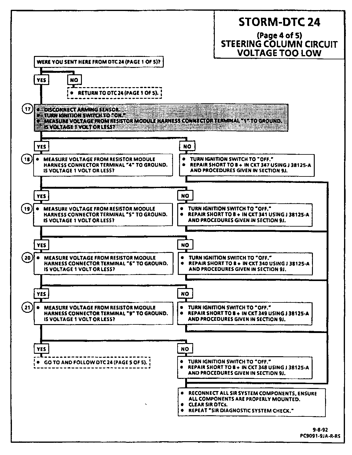
Test Description: Number(s) below refer to circled number(s) on the diagnostic chart.
17. This test checks for a short to B + in CKT 347. 18. This test checks for a short to B + in CKT 341. 19. This test checks for a short to B + in CKT 340. 20. This test checks for a short to B + in CKT 349. 21. This test checks for a short to B + in CKT 348.


General Motors bulletins are intended for use by professional technicians, not a "do-it-yourselfer". They are written to inform those technicians of conditions that may occur on some vehicles, or to provide information that could assist in the proper service of a vehicle. Properly trained technicians have the equipment, tools, safety instructions and know-how to do a job properly and safely. If a condition is described, do not assume that the bulletin applies to your vehicle, or that your vehicle will have that condition. See a General Motors dealer servicing your brand of General Motors vehicle for information on whether your vehicle may benefit from the information.
