GM Service Manual Online
For 1990-2009 cars only

Connector Repairs contains a list of all connector repairs. The connector repairs are listed by the connector manufacturer and then by connector type. If the technician cannot identify the manufacturer of the connector, refer to Identifying Connectors below. Knowing the connector manufacturer will assist in finding the correct connector repair from the following list:
    •  Connector Position Assurance Locks
    •  Terminal Position Assurance Locks
    •  Bosch Connectors
    •  Delphi Connectors
    •  Tyco/AMP Connectors
    •  Yazaki Connectors
    •  Repairing Connector Terminals

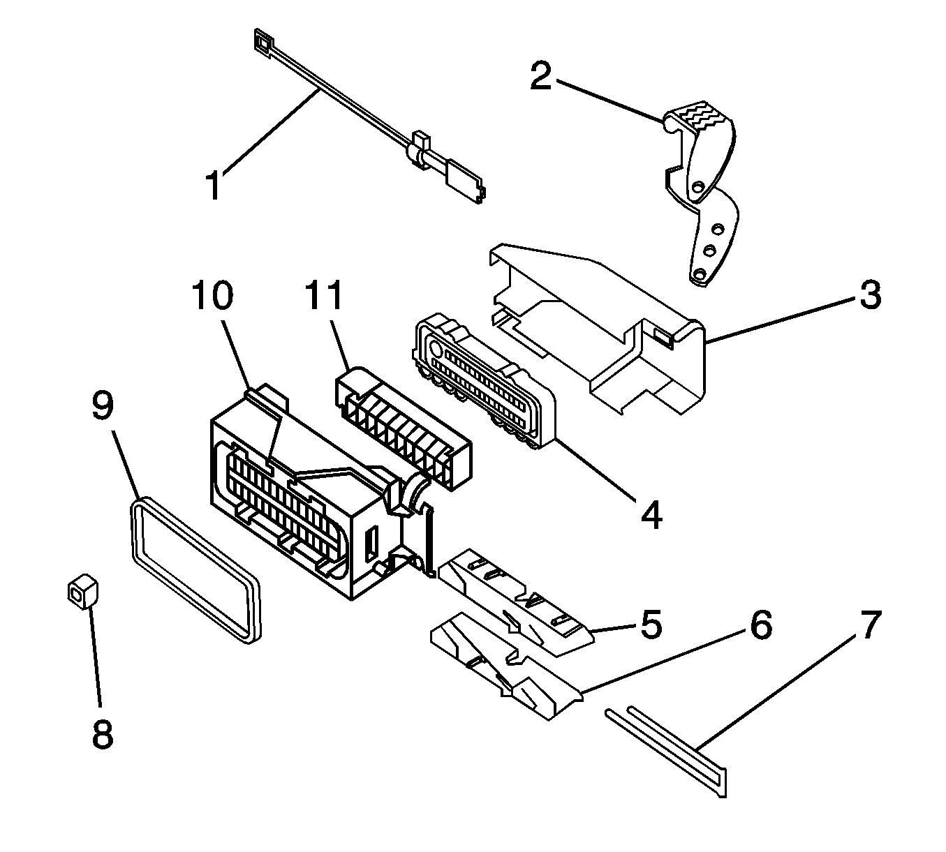
Connector Anatomy


Object Number: 1709341  Size: SH
(1)Connector Positive Assurance (CPA)
(2)Assist Lever
(3)Wiredress Cover
(4)Seal Strain/Relief
(5)Slide Left Hand
(6)Slide Right Hand
(7)Terminal Positive Assurance (TPA)
(8)Terminal Positive Assurance (TPA)
(9)Connector Seal
(10)Connector Housing
(11)Inner Connector

Identifying Connectors

Knowing the connector manufacturer is helpful when trying to locating the correct connector repair procedure. There are many different connector designs used on GM vehicles and it is sometimes difficult to identify the connector manufacturer. The information in this document should help with the identification of connector manufactures.

The following connector manufacturers make most of the connectors found in GM vehicles:

    • AFL/EPC (Alcoa Fujikura Ltd./Engineered Plastics Components)
    • Bosch
    • Delphi
    • FCI (Framatome Connectors International)
    • JAE (Japan Aviation Electronics)
    • JST (Japan Solderless Terminals)
    • Kostel
    • Molex
    • Sumitomo
    • Tyco/AMP
    • Yazaki

Identifying the manufacturer of a connector is often difficult. When trying to determine the manufacturer of a connector, look for specific identifying marks that are unique to that connector supplier. Most of these identify marks are hard to find or see. Check the connector carefully and refer to the information below for pictures and descriptions of connector identification markings.


Object Number: 1466850  Size: SH
    • Most of AFLs connectors have EPC on their connector body. Some of the smaller connectors will not have any markings on them.

Object Number: 1460356  Size: SH
    • In some cases Bosch will actually be printed on the connector. If Bosch does not appear on the connector, look for the Bosch logo. The Bosch logo is a circle with a blunted arrow inside. This logo can appear anywhere on the connector and is often very small.

Object Number: 1460486  Size: SH
    • In some cases Delphi will actually be printed on the connector. If Delphi is not printed on the connector, look for PED. In both cases there is no specific orientation for Delphi or PED and they can appear anywhere on the connector.

Object Number: 1460611  Size: SH
    • FCI connectors may have the FCI logo on their connectors. The logo is the letters FCI with an "A" above it.

Object Number: 1468768  Size: SH
    • JAE connector have JAE in small letters on their connectors.

Object Number: 1468706  Size: SH
    • JST connectors have JST in small letters on their connectors, similar to that above. The location of the logo will vary with the connector size and style.

Object Number: 1709340  Size: SH
    • Kostel has an "LK" with a circle around it. These connector are usually used as a transmissions connection.

Object Number: 1467199  Size: SH
    • Most Molex connectors will have the Molex logo on the dresscover of the connector. In some cases the connectors may have MX followed by another letter. The third letter indicates where the connector was made. A connector with MXD is a Molex connector made in Detroit.

Object Number: 1467225  Size: SH
    • Sumitomo has a unique symbol on their connector and possibly a part number. The symbol is similar to that of a diamond lying on its side, similar to that shown. The logo could appear anywhere but the most common place is at the wire side of the housing.
    • Tyco/AMP has many different and unique connector designs. Some may or may not have identifiable marks on them.

Object Number: 1467254  Size: SH
    • Yazaki has a wedge or arrow shape, similar to that shown.

Connector Repairs AMP

Tools Required

J-38125 Terminal Repair Kit

Removal Procedure


Object Number: 1709293  Size: SH

Side view of connector.


Object Number: 1709294  Size: SH

View of top of connector.

  1. Locate the assist lever and lock on the top of the connector.

  2. Object Number: 1709295  Size: SH
  3. While depressing the lock, pull the lever over and past the lock.

  4. Object Number: 1709296  Size: SH
  5. Disconnect the connector from the component.

  6. Object Number: 1709297  Size: SH
  7. Locate the dress cover locking tabs at the rear of the connector. Use a small flat-blade tool to release the locking tabs. Repeat this procedure for the other locking tab.

  8. Object Number: 1709298  Size: SH
  9. Once the locking tabs are unlocked, slide the inner connector out of the rear of the connector housing.

  10. Object Number: 1709299  Size: SH
  11. Use the J 38125-12A (GM P/N 12094429) tool to release the terminals by pressing on the tang. See the release tool cross reference in the Reference Guide of the J-38125 to ensure that the correct release tool is used.
  12. While holding the removal tool in place, gently pull the wire out of the back of the connector. Always remember never use force when pulling a terminal out of a connector.

Repair Procedure

Use the appropriate terminal and follow the instructions in the J-38125 .

Location of the terminal in the repair tray and the proper crimp tool can be found in the appropriate connector end view.

Connector Repairs AFL

Tools Required

J-38125 Terminal Repair Kit

Removal Procedure

Follow the steps below in order to remove terminals from the connector.


    Object Number: 1709283  Size: SH
  1. For connectors with a bolt in the dress cover, turn the bolt counter clockwise to remove the connector from the component.

  2. Object Number: 1709284  Size: SH
  3. Locate the CPA on the top of the wire dress cover. Slide the CPA forward.

  4. Object Number: 1709285  Size: SH
  5. Slide the lever lock forward while pressing down on the lever lock release tab.

  6. Object Number: 1709286  Size: SH
  7. View showing depressing of the lever lock release tab.

  8. Object Number: 1709287  Size: SH
  9. View of connector in released position.
  10. Disconnect the connector from the component.
  11. Locate the dress cover locking tabs at the corners of the dress cover. Use a small flat-blade tool to release the locking tabs and remove the dress cover.

  12. Object Number: 1709288  Size: SH
  13. Release the rear lower half of the wiredress cover.

  14. Object Number: 1709289  Size: SH
  15. Release the tabs that are holding the wiredress cover to the connector body.
  16. Remove the nose piece by inserting a small flat-blade tool into the slots on both ends of the connector body. Gently pry the nose piece out of the connector. J 38125-216 can also be used to remove the nose piece.

  17. Object Number: 1709282  Size: SH
  18. Use the J 38125-12A (GM P/N 12094429) tool to release the terminals by lifting the terminal retaining tabs on the inside of the connector. See the release tool cross reference in the Reference Guide of the J-38125 to ensure that the correct release tool is used.

  19. Object Number: 1709281  Size: SH
  20. While holding the removal tool in place, gently pull the wire out of the back of the connector. Always remember never use force when pulling a terminal out of a connector.

Repair Procedure

Use the appropriate terminal and follow the instructions in the J-38125 .

Location of the terminal in the repair tray and the proper crimp tool can be found in the appropriate connector end view.

Connector Repairs Bosch

Tools Required

J-38125 Terminal Repair Kit

Removal Procedure


    Object Number: 1709276  Size: SH
  1. Locate the assist lever on the top of the connector. Move the assist lever to the forward position.

  2. Object Number: 1709277  Size: SH
  3. Disconnect the connector from the component.

  4. Object Number: 1709273  Size: SH
  5. Locate the dress cover locking tabs at the corners of the connector. Use a small flat-blade tool to release the locking tabs and remove the dress cover.

  6. Object Number: 1709274  Size: SH
  7. The terminal positive assurance (TPA) is located in the front of the connector.

  8. Object Number: 1709278  Size: SH
  9. Use a small flat-blade tool to remove TPA from the connector.

  10. Object Number: 1709275  Size: SH
  11. Use the J 38125-213 or the J 38125-556 (GM P/N 12093647) tool to release the terminals by inserting the tool into the terminal release cavity. See the release tool cross reference in the Reference Guide of the J-38125 to ensure that the correct release tool is used.
  12. While holding the removal tool in place, gently pull the wire out of the back of the connector. Always remember never use force when pulling a terminal out of a connector.

Repair Procedure


Object Number: 1709277  Size: SH

Important: Ensure that the dress cover and connector body are both in the released position before reassembling. Failure to do so may cause damage to the connector and component.

Use the appropriate terminal and follow the instructions in the J-38125 .

Location of the terminal in the repair tray and the proper crimp tool can be found in the appropriate connector end view.

Connector Repairs Delphi 12

Tools Required

J-38125 Terminal Repair Kit

Removal Procedure

Follow the steps below in order to remove terminals from the connector.


    Object Number: 1709308  Size: SH
  1. Locate the lever lock on the wire dress cover. Remove the CPA and slide the lever lock away from the connector body.
  2. Disconnect the connector from the component.

  3. Object Number: 1709309  Size: SH
  4. Locate the dress cover locking tabs on the dress cover of the connector. Using a small flat-blade tool release all of the locking tabs.

  5. Object Number: 1709311  Size: SH
  6. Release the lower wiredress cover locking tab.

  7. Object Number: 1709312  Size: SH
  8. Release the upper wiredress cover locking tab.
  9. Once the locks are unlocked, lift the dress cover off.

  10. Object Number: 1709313  Size: SH

    Important: Always use care when removing a terminal position assurance (TPA) in order to avoid damaging it.

  11. Remove the TPA by inserting a small flat-blade tool into the locking tabs on both sides of the TPA . Gently pry the TPA out of the connector.

  12. Object Number: 1709314  Size: SH
  13. Remove the nose piece by inserting a small flat-blade tool into the locking tabs on both sides of the nose piece. Gently pry the nose piece out of the connector.

  14. Object Number: 1709315  Size: SH
  15. Insert the J 38125-12A (GM P/N 12094429) tool to release the terminals by inserting the tool into the terminal release cavity. See the release tool cross reference in the Reference Guide of the J-38125 to ensure that the correct release tool is used.

  16. Object Number: 1709316  Size: SH
  17. While holding the removal tool in place, gently pull the wire out of the back of the connector. Always remember never use force when pulling a terminal out of a connector.

Repair Procedure

Use the appropriate terminal and follow the instructions in the J-38125 .

Location of the terminal in the repair tray and the proper crimp tool can be found in the appropriate connector end view.

Connector Repairs FCI

Tools Required

J-38125 Terminal Repair Kit

Removal Procedure

Follow the steps below in order to remove terminals from the connector.

  1. Slide the lever lock forward while pressing down on the lever lock release tab.

  2. Object Number: 1709268  Size: SH
  3. The release tab is located on the top of the wiredress cover.

  4. Object Number: 1709269  Size: SH
  5. View of connector in released position.
  6. Disconnect the connector from the component.
  7. Locate the dress cover locking tabs at the corners of the dress cover. Use a small flat-blade tool to release the locking tabs and remove the dress cover.

  8. Object Number: 1709270  Size: SH
  9. Use a small flat-blade tool to slide the TPA up one notch on both ends of the connector. The TPA is located underneath the wire dress cover.

  10. Object Number: 1709271  Size: SH
  11. For the larger terminals insert the J 38125-556 (GM P/N 12093647) tool to release the terminals by inserting the tool into the terminal release cavity. For the smaller terminals insert the J 38125-560 (GM P/N 15314260) tool to release the terminals by inserting the tool into the terminal release cavity. See the release tool cross reference in the Reference Guide of the J-38125 to ensure that the correct release tool is used.

  12. Object Number: 1709272  Size: SH
  13. While holding the removal tool in place, gently pull the wire out of the back of the connector. Always remember never use force when pulling a terminal out of a connector.

Repair Procedure

Use the appropriate terminal and follow the instructions in the J-38125 .

Location of the terminal in the repair tray and the proper crimp tool can be found in the appropriate connector end view.

Connector Repairs Lear

Tools Required

J-38125 Terminal Repair Kit

Removal Procedure


Object Number: 1709300  Size: SH

View of typical connector.


Object Number: 1709301  Size: SH

View of connector in released position.

  1. Locate the assist lever at the back of the connector. Move the assist lever to the rear position.
  2. Disconnect the connector from the component.

  3. Object Number: 1709302  Size: SH
  4. Use a small flat-blade tool to remove the dress cover.

  5. Object Number: 1709303  Size: SH
  6. Slide the dress cover forward and off of the connector.

  7. Object Number: 1709304  Size: SH
  8. The terminal positive assurance (TPA) is located in the front and rear of the connector.

  9. Object Number: 1709305  Size: SH
  10. Use a small flat-blade tool to remove the rear TPA from the connector.
  11. Important: The front TPA cannot be removed from the connector. Only move it to the release point.

  12. Use a small flat-blade tool to move the front TPA to the release position.

  13. Object Number: 1709306  Size: SH
  14. Use the J 38125-213 or the J 38125-560 (GM P/N 15314260) tool to release the terminals by inserting the tool into the terminal release cavity. See the release tool cross reference in the Reference Guide of the J-38125 to ensure that the correct release tool is used.
  15. While holding the removal tool in place, gently pull the wire out of the back of the connector. Always remember never use force when pulling a terminal out of a connector.

Repair Procedure

Use the appropriate terminal and follow the instructions in the J-38125 .

Location of the terminal in the repair tray and the proper crimp tool can be found in the appropriate connector end view.

Connector Repairs Molex

Tools Required

J-38125 Terminal Repair Kit

Removal Procedure

Follow the steps below in order to remove terminals from the connector.


    Object Number: 1709256  Size: SH
  1. Locate the CPA on the top of the wire dress cover. Slide the CPA forward.

  2. Object Number: 1709257  Size: SH
  3. Slide the lever lock forward while pressing down on the lever lock release tab.

  4. Object Number: 1709258  Size: SH
  5. The lever lock release tab is located on top of the wiredress cover.

  6. Object Number: 1709259  Size: SH
  7. View of connector in the released position.
  8. Disconnect the connector from the component.
  9. Position the lever lock in the middle of the connector.

  10. Object Number: 1709260  Size: SH
  11. Slide the dress cover forward and off of the connector body.

  12. Object Number: 1709262  Size: SH
  13. Remove the nose piece by inserting a small flat-blade tool into the indentations on both ends of the connector body. Gently pry the nose piece out of the connector.

  14. Object Number: 1709266  Size: SH
  15. Use the J 38125-12A (GM P/N 12094429) tool to release the terminals by lifting the terminal retaining tabs on the inside of the connector. See the release tool cross reference in the Reference Guide of the J-38125 to ensure that the correct release tool is used.

  16. Object Number: 1709263  Size: SH
  17. While holding the removal tool in place, gently pull the wire out of the back of the connector. Always remember never use force when pulling a terminal out of a connector.

Repair Procedure

Use the appropriate terminal and follow the instructions in the J-38125 .

Location of the terminal in the repair tray and the proper crimp tool can be found in the appropriate connector end view.

Connector Repairs Tyco

Tools Required

J-38125 Terminal Repair Kit

Removal Procedure

Follow the steps below in order to remove terminals from the connector.

  1. Locate the lever lock on the wire dress cover. Slide the lever lock away from the connector body.
  2. Disconnect the connector from the component.
  3. Locate the dress cover locking tabs on the dress cover of the connector. Using a small flat-blade tool release all of the locking tabs.
  4. Once the locks are unlocked, lift the dress cover off.

  5. Object Number: 1709323  Size: SH

    Important: Always use care when removing a terminal position assurance (TPA) in order to avoid damaging it.

  6. Release the TPA by inserting a small flat-blade tool into the blue locking tabs on both ends of the connector. Gently slide the TPA up to the released position on both ends.

  7. Object Number: 1709325  Size: SH
  8. For the larger terminals insert the J 38125-13A (GM P/N 12031876-1) tool to release the terminals by inserting the tool into the terminal release cavity. For the smaller terminals insert the J 38125-12A (GM P/N 12094429) tool to release the terminals by inserting the tool into the terminal release cavity. See the release tool cross reference in the Reference Guide of the J-38125 to ensure that the correct release tool is used.

  9. Object Number: 1709326  Size: SH
  10. View of the release tool being used for the larger terminals.

  11. Object Number: 1709327  Size: SH
  12. View of the release tool being used for the larger terminals.

  13. Object Number: 1709328  Size: SH
  14. View of the release tool being used for the smaller terminals.
  15. While holding the removal tool in place, gently pull the wire out of the back of the connector. Always remember never use force when pulling a terminal out of a connector.

Repair Procedure

Use the appropriate terminal and follow the instructions in the J-38125 .

Location of the terminal in the repair tray and the proper crimp tool can be found in the appropriate connector end view.

Connector Repairs Yazaki

Tools Required

J-38125 Terminal Repair Kit

Removal Procedure

  1. While depressing the lock, pull the two connector halves apart.

  2. Object Number: 1709336  Size: SH
  3. Use a small flat-blade tool to very carefully push the TPA towards the face of the connector on both sides of the connector.
  4. Important: The TPA is fragile and may break if not done carefully.


    Object Number: 1709329  Size: SH
  5. View of the male half of the connector with female terminals.

  6. Object Number: 1709335  Size: SH
  7. View of the female half of the connector with male terminals.
  8. Use the J 38125-215 tool to release the terminals by inserting the tool into the terminal release cavity. See the release tool cross reference in the Reference Guide of the J-38125 to ensure that the correct release tool is used.

  9. Object Number: 1709332  Size: SH
  10. View of the female half of the connector with male terminals.

  11. Object Number: 1709331  Size: SH
  12. View of the male half of the connector with female terminals.
  13. While holding the removal tool in place, gently pull the wire out of the back of the connector. Always remember never use force when pulling a terminal out of a connector.

Repair Procedure

Use the appropriate terminal and follow the instructions in the J-38125 .

Location of the terminal in the repair tray and the proper crimp tool can be found in the appropriate connector end view.