DTC P0751 1-2 Shift Solenoid Valve Performance 5.7 and 7.4L Gas
| Table 1: | Shift Solenoid State and Gear Ratio Table |
| Table 2: | DTC P0751 1-2 Shift Solenoid Valve Performance (5.7L and 7.4L Gas) |
Circuit Description
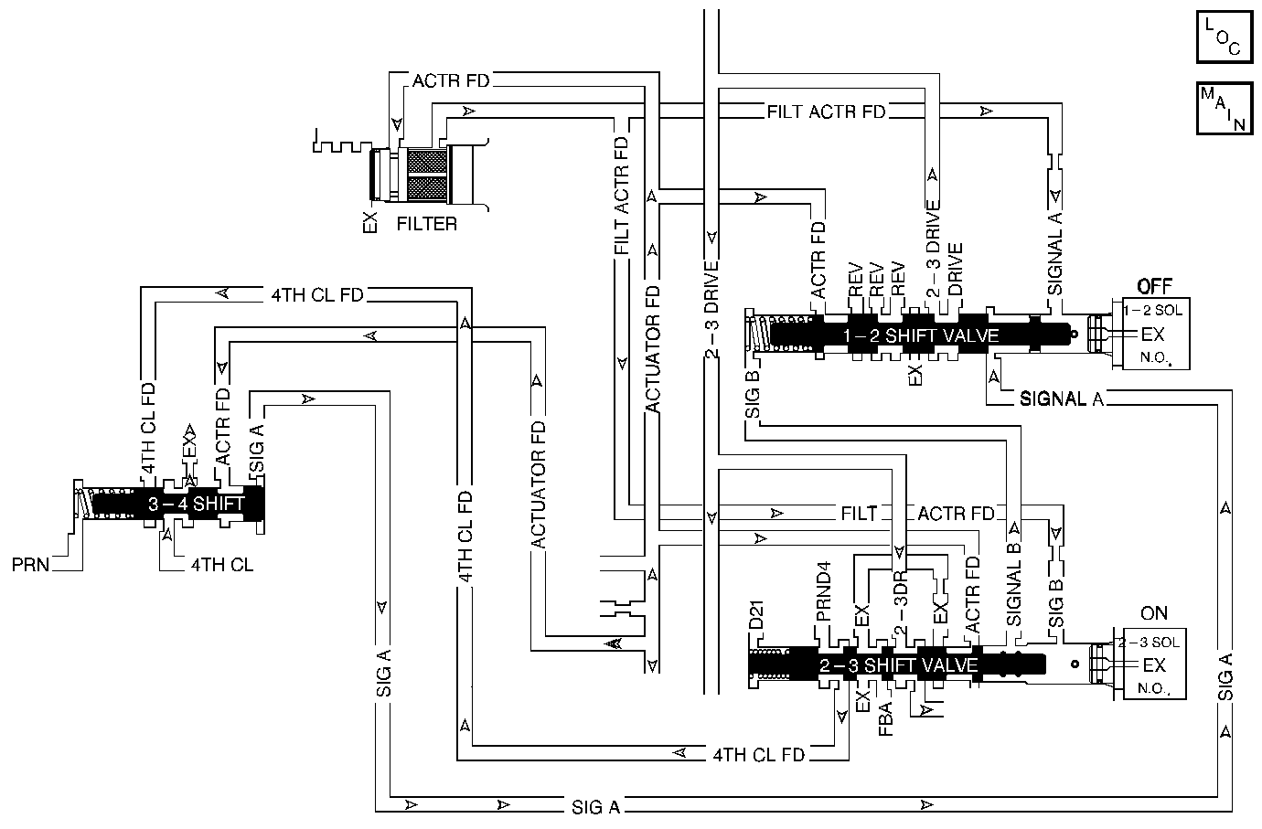
The 1-2 Shift Solenoid Valve (1-2 SS Valve) controls the fluid flow action on the 1-2 and the 3-4 shift valves. The 1-2 SS Valve is a normally-open exhaust valve that is used with the 2-3 shift solenoid Valve (2-3 SS Valve) to allow four different shifting combinations.
When the VCM detects an incorrect Gear Ratio, then DTC P0751 sets. DTC P0751 is a type A DTC.
Conditions for Setting the DTC
| • | No MAP Sensor DTCs P0106, P0107 or P0108. |
| • | No TP Sensor DTCs P0121, P0122 or P0123. |
| • | No VSS DTC P0502. |
| • | No ISS Sensor DTCs P0716 or P0717. |
| • | No 1-2 SS Valve DTC P0753. |
| • | No 2-3 SS Valve DTC P0758. |
| • | No TFP Val. Position Sw. DTC P1810. |
| • | No Four Wheel Drive DTC P1875. |
| • | The engine must be running for 5 seconds and not in fuel cutoff. |
| • | The vehicle speed is greater than 4.2 km/h (2.5 mph). |
| • | The TP Sensor is greater than 12%. |
| • | The Engine Torque is 70 lb ft (88 N·m) to the following: |
| - | 275 lb ft (345 N·m) 4.3L |
| - | 375 lb ft (470 N·m) 5.7L |
| - | 500 lb ft (627 N·m) 7.4L. |
| • | The transmission fluid temperature is greater than 20°C (68°F). |
| • | The engine speed is less than 3650 RPM. |
| • | Do not put in to Four Wheel Drive Low. |
| • | All the above conditions are met and one of the following conditions are met: |
| - | When the 1-2 SS Valve is stuck OFF, first gear is commanded and the ratio is equal to second gear for greater than 2.0 seconds. (2.5 seconds for 4.3L) and 4th gear is commanded with the TCC locked and the ratio equals 3rd for greater than 3 seconds. |
| - | When the 1-2 SS Valve is stuck ON, second gear is commanded and the ratio is equal to first gear for greater than 3 seconds. |
Action Taken When the DTC Sets
| • | The VCM commands maximum line pressure. |
| • | The VCM freezes shift adapts. |
| • | The VCM illuminates the Malfunction Indicator Lamp (MIL) for California emissions vehicles. |
Conditions for Clearing the DTC
| • | For California emissions only, the VCM turns OFF the MIL after three consecutive ignition cycles without a failure reported. |
| • | A scan tool can clear the DTC from the VCM history. The VCM clears the DTC from the VCM history if the vehicle completes 40 warm-up cycles without a failure reported. |
| • | The VCM cancels the DTC default actions when the fault no longer exists and the ignition is OFF long enough in order to power down the VCM. |
Diagnostic Aids
| • | Verify that the transmission meets the specifications in the 4L80-E shift speed table. |
| • | Other internal transmission failures can cause more than one shift to occur. |
| • | First diagnose and clear any engine DTCs or TP Sensor codes that are present. Then inspect for any transmission DTCs that may have reset. |
Gear | 1-2 SS Valve | 2-3 SS Valve | Gear Ratio |
|---|---|---|---|
1 | ON | OFF | 2.48:1 |
2 | OFF | OFF | 1.48:1 |
3 | OFF | ON | 1.00:1 |
4 | ON | ON | 0.75:1 |
Test Description
The numbers below refer to the step numbers on the diagnostic table.
-
This step tests the function of the TFP Val. Position Sw.
-
This step tests whether the scan tool commanded all the shifts, or whether all the shift solenoids responded correctly but all the shifts did not occur.
Step | Action | Value(s) | Yes | No | ||||
|---|---|---|---|---|---|---|---|---|
1 | Was the Powertrain On-Board Diagnostic (OBD) System Check performed? | -- | ||||||
Important: Before clearing the DTCs, use the scan tool in order to record the Freeze Frame and Failure Records for reference. The Clear Info function will erase the data. Does each selected transmission range match the Trans Range on the scan tool? | -- | |||||||
Did you detect a 2-2-3-3 or 1-1-4-4 shift pattern only? (You may need to road test the vehicle). | -- | Go to Diagnostic Aids | ||||||
4 |
Did you find and correct a condition? | -- | -- | |||||
5 | In order to verify your repair, perform the following procedure:
Has the test run and passed? | -- | System OK |
DTC P0751 1-2 Shift Solenoid Valve Performance 6.5L Diesel
| Table 1: | Shift Solenoid State and Gear Ratio Table |
| Table 2: | DTC P0751 1-2 Shift Solenoid Valve Performance (6.5L Diesel) |
Circuit Description
The 1-2 Shift Solenoid Valve (1-2 SS Valve) controls the fluid flow action on the 1-2 and the 3-4 shift valves. The 1-2 SS Valve is a normally-open exhaust valve that is used with the 2-3 shift solenoid Valve (2-3 SS Valve) to allow four different shifting combinations.
When the PCM detects incorrect Gear Ratios, then DTC P0751 sets. DTC P0751 is a type D DTC. For California emissions vehicles DTC P0751 is a type A DTC.
Conditions for Setting the DTC
| • | No MAP Sensor DTCs P0106, P0107 or P0108. |
| • | No APP Sensor DTCs P0121, P0122, P0123, P0220, P0221, P0222, P0223, P0225, P0226, P0227 or P0228. |
| • | No OSS DTCs P0722 or P0723. |
| • | No ISS Sensor DTCs P0716 or P0717. |
| • | No 1-2 SS Valve DTC P0753. |
| • | No 2-3 SS Valve DTC P0758. |
| • | No TFP Val. Position Sw. DTC P1810. |
| • | No Four Wheel Drive DTC P1875. |
| • | The engine must be running. |
| • | The vehicle speed is greater than 4.2 km/h (2.5 mph). |
| • | The APP Sensor is greater than 12%. |
| • | The Engine Torque is 60-450 lb ft. |
| • | No engine torque malfunctions. |
| • | The transmission fluid is greater than 20°C (68°F). |
| • | The engine speed is less than 3650 RPM. |
| • | Do not put in to Four Wheel Drive Low. |
| • | All the above conditions are met and one of the following conditions are met: |
Stuck Off: (after two occurrences)
| - | First gear is commanded and the ratio is equal to second gear for greater than 1.7 seconds. |
| - | Fourth gear is commanded (with TCC locked) and the ratio equals third gear for greater than 3 seconds. |
Stuck On: (after five occurrences)
| - | Second gear is commanded and the ratio equals first gear for greater than 2.5 seconds. |
| - | Condition is met with 5 occurrences. |
Action Taken When the DTC Sets
| • | The PCM commands maximum line pressure. |
| • | The PCM freezes shift adapts. |
| • | The PCM illuminates the Malfunction Indicator Lamp (MIL). |
Conditions for Clearing the MIL/DTC
| • | The PCM turns OFF the MIL after three consecutive ignition cycles without a failure reported. |
| • | A scan tool can clear the DTC from the PCM history. The PCM clears the DTC from the PCM history if the vehicle completes 40 warm-up cycles without a failure reported. |
| • | The PCM cancels the DTC default actions when the fault no longer exists and the ignition is OFF long enough in order to power down the PCM. |
Diagnostic Aids
| • | Verify that the transmission meets the specifications in the 4L80-E shift speed table. |
| • | Other internal transmission failures can cause more than one shift to occur. |
| • | First diagnose and clear any engine DTCs or APP Sensor codes that are present. Then inspect for any transmission DTCs that may have reset. |
Gear | 1-2 SS Valve | 2-3 SS Valve | Gear Ratio |
|---|---|---|---|
1 | ON | OFF | 2.48:1 |
2 | OFF | OFF | 1.48:1 |
3 | OFF | ON | 1.00:1 |
4 | ON | ON | 0.75:1 |
Test Description
The numbers below refer to the step numbers on the diagnostic table.
-
This step tests the function of the TFP Val. Position Sw.
-
This step tests whether the scan tool commanded all the shifts, or whether all the shift solenoids responded correctly but all the shifts did not occur.
Step | Action | Value(s) | Yes | No | ||||
|---|---|---|---|---|---|---|---|---|
1 | Was the Powertrain On-Board Diagnostic (OBD) System Check performed? | -- | ||||||
Important: Before clearing the DTCs, use the scan tool in order to record the Freeze Frame and Failure Records for reference. The Clear Info function will erase the data. Does each selected transmission range match the Trans Range on the scan tool? | -- | |||||||
Did you detect a 2-2-3-3 or 1-1-4-4 shift pattern only? (You may need to road test the vehicle). | -- | Go to Diagnostic Aids | ||||||
4 |
Refer to the diagnosis tables. Did you find and correct a condition? | -- | -- | |||||
5 | In order to verify your repair, perform the following procedure:
Has the test run and passed? | -- | System OK |
