For 1990-2009 cars only
Removal Procedure
Notice: When raising or supporting the engine for any reason, do not use a jack under the oil pan, any sheet metal, or the crankshaft pulley. Due to the small clearance between the oil pan and the oil pump screen, jacking against the oil pan may cause the pan to be bent against the pump screen. This will result in a damaged oil pickup unit.
- If vehicle is a 2-wheel drive (2WD), raise the vehicle to a height to work through the front wheelhouse opening.
- If vehicle is a 4-wheel drive (4WD), raise the vehicle in order to remove the front tires and wheels.
- Remove the left front tire and wheel. Refer to Tire and Wheel Removal and Installation .
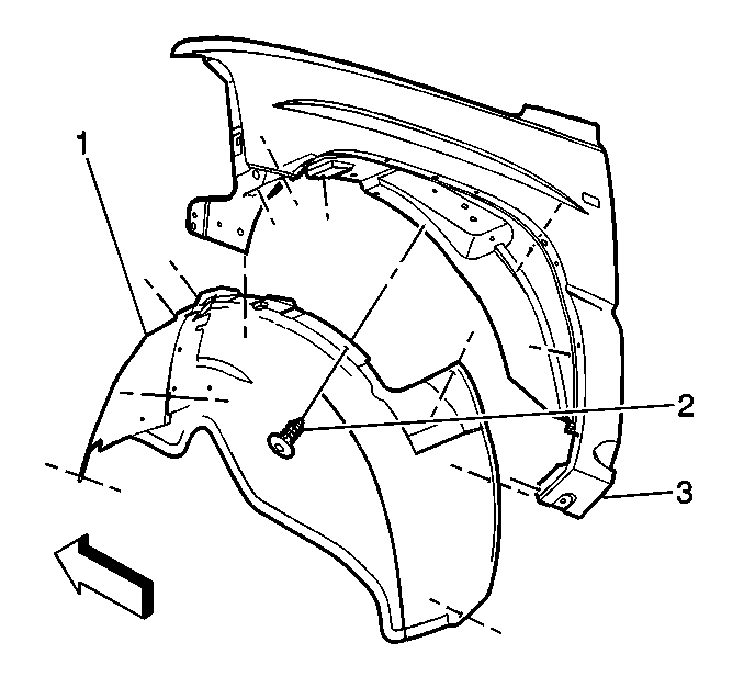
- Remove the wheelhouse inner panel push pin retainers (2).
- Remove the wheelhouse inner panel (1).
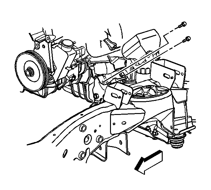
- Working through the wheelhouse opening, remove the engine mount heat shield bolts.
- Remove the engine mount heat shield.
- Remove the engine mount-to-engine mount bracket bolt.
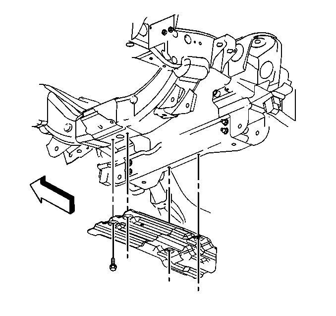
- if equipped, remove the oil pan skid plate bolts and plate.
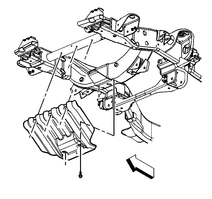
- Remove the engine shield bolts and shield.
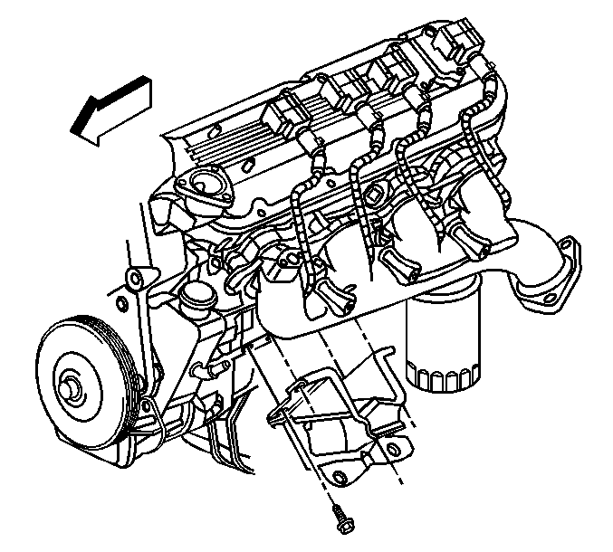
- Raise the engine with a suitable jack in order to remove the engine mount and bracket.
- Remove the engine mount-to-engine bolts.
- Remove the engine mount.
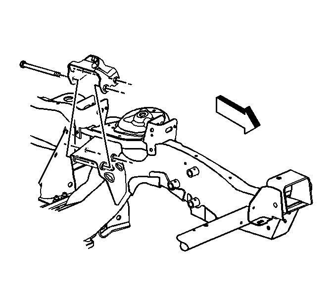
- Remove the engine mount bracket through bolts.
- Remove the engine mount bracket.
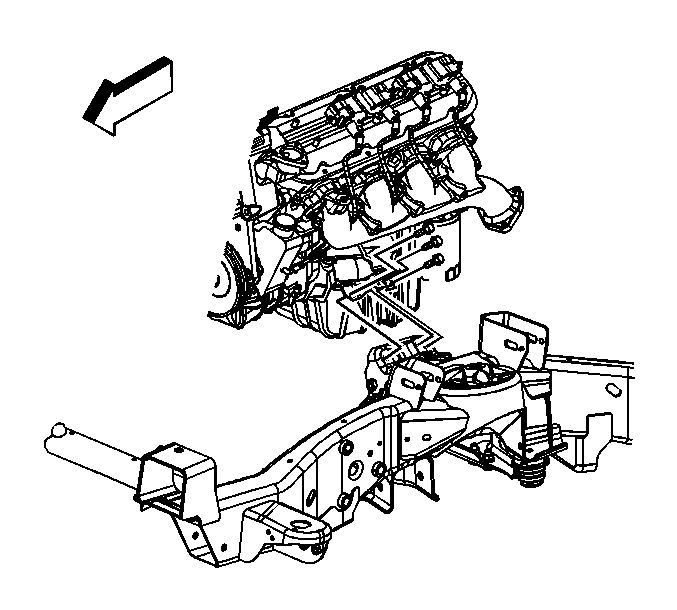
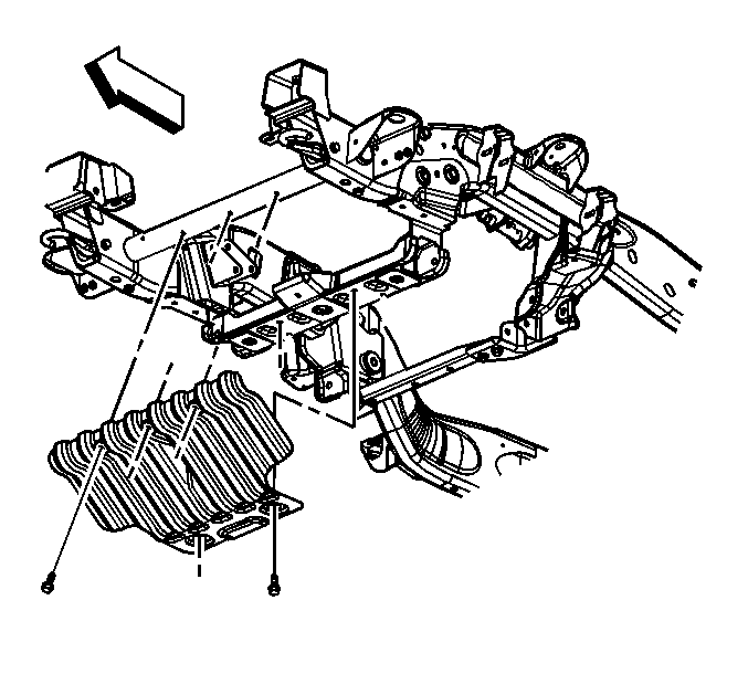
Important: When raising the engine only raise it enough to separate the engine mount from the engine mount bracket.
Installation Procedure
- Install the engine mount bracket onto the frame.
- Perform the following procedure prior to installing the engine mount bracket bolts.
- Loosely install the engine mount bracket through bolts.
- Position the engine mount to engine.
- Loosely install the engine mount-to-engine bolts.
- Tighten the engine mount bracket through bolts and engine mount-to-engine bolts.
- Install the engine shield and bolts.
- Lower the engine.
- if equipped, install the oil pan skid plate and bolts.
- Install the engine mount heat shield.
- Install the engine mount-to-engine mount bracket bolts.
- Install the wheelhouse inner panel (1).
- Install the wheelhouse inner panel push pin retainers (2).
- Install the left front tire and wheel. Refer to Tire and Wheel Removal and Installation .
- Lower the vehicle.

| • | Remove all traces of the original adhesive patch. |
| • | Clean the threads of the bolt with denatured alcohol or equivalent and allow to dry. |
| • | Apply threadlocker to the bolts. Refer to Adhesives, Fluids, Lubricants, and Sealers for the correct part number. |

Notice: Refer to Fastener Notice in the Preface section.
Tighten
| • | Tighten the engine mount bracket through bolts to 75 N·m (55 lb ft). |
| • | Tighten the engine mount-to-engine bolts to 50 N·m (37 lb ft). |
Tighten
Tighten the engine shield bolts to 20 N·m (15 lb ft).

Tighten
Tighten the oil pan skid plate bolts to 20 N·m (15 lb ft).


Tighten
Tighten the engine mount-to-engine mount bracket bolts to 65 N·m (48 lb ft).

