For 1990-2009 cars only
Fuel Hose/Pipes Replacement - Chassis 1500 Series
Removal Procedure
Important: Clean all fuel and evaporative emission (EVAP) lines connections and surrounding areas prior to disconnecting the lines in order to avoid possible fuel and/or EVAP system contamination.
- Relieve the fuel system pressure. Refer to the Fuel Pressure Relief .
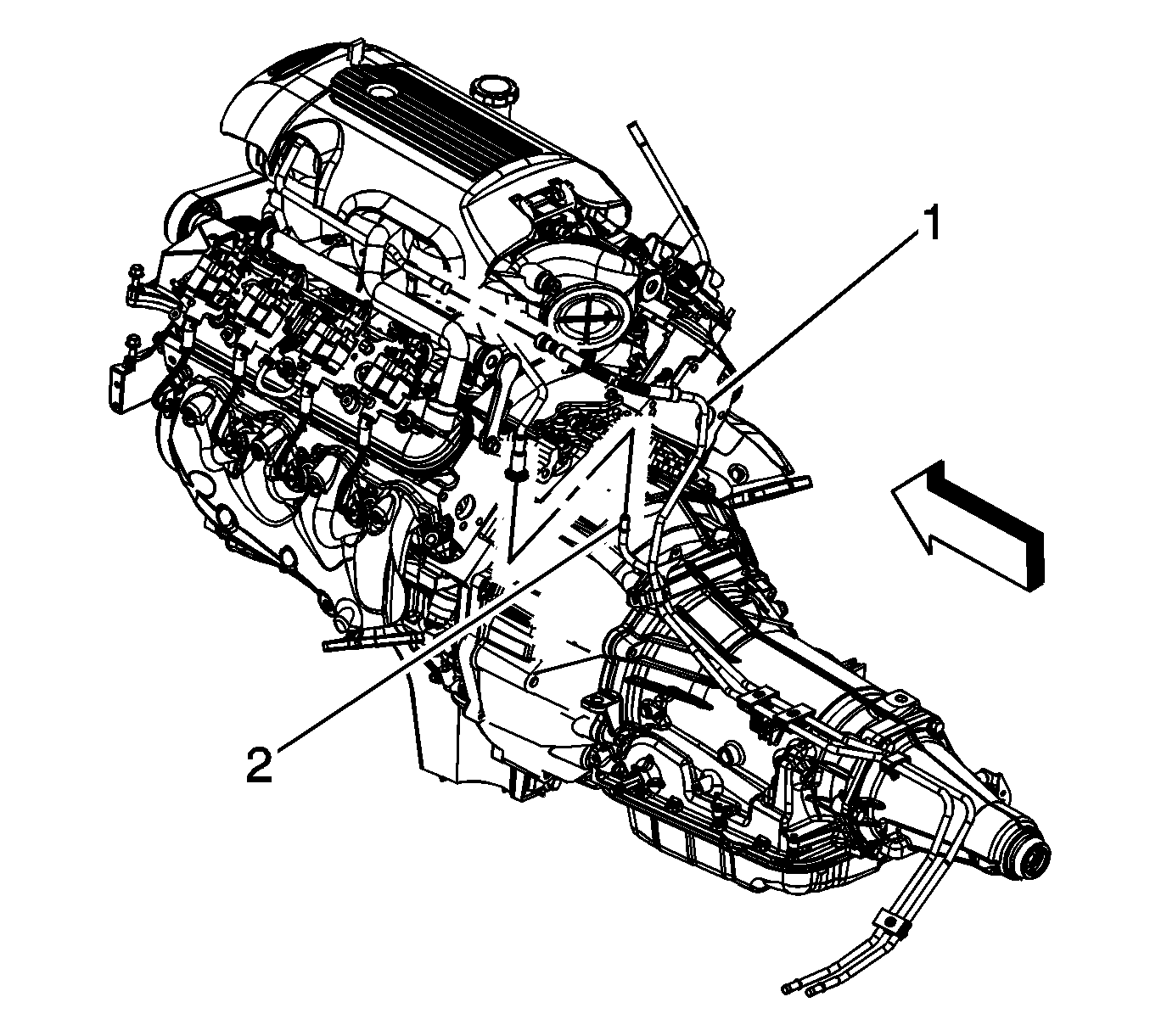
- Disconnect the fuel feed pipe (1) at the fuel rail. Refer to Metal Collar Quick Connect Fitting Service .
- Disconnect the evaporative emission (EVAP) canister purge pipe (2).
- Cap the fuel rail and EVAP pipes.
- Raise and suitably support the vehicle. Refer to Lifting and Jacking the Vehicle in General Information.
- Unbolt and reposition the front propeller shaft. Refer to Front Propeller Shaft Replacement in Propeller Shaft.
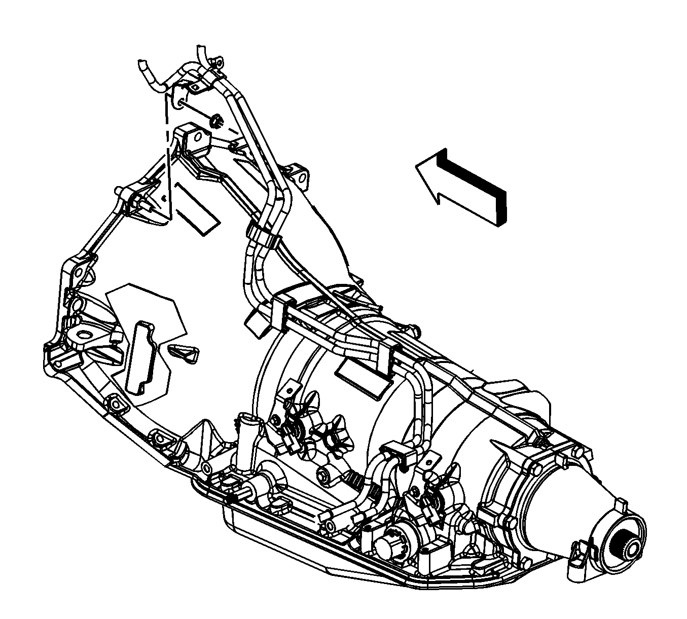
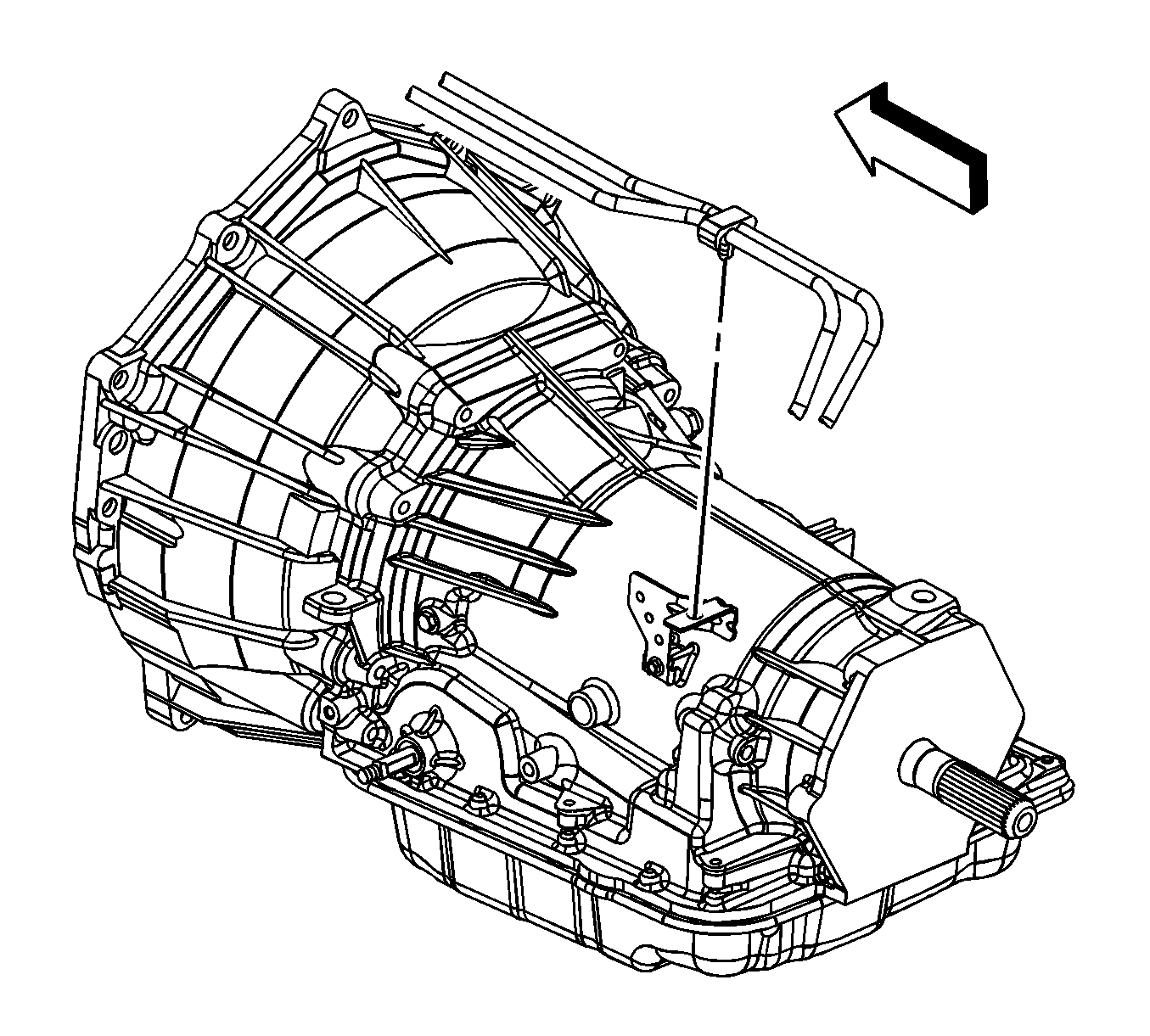
- Remove the fuel pipe bracket nut.
- Remove the fuel pipe bracket from the bellhousing stud.
- Remove the fuel line clip from the bracket on the automatic transmission.
- If equipped with 4-wheel drive (4WD), remove the fuel hose/pipe clip from the bracket on the transfer case.
- Remove the fuel line bracket bolt.
- Disconnect the fuel feed and EVAP lines from the fuel tank lines. Refer to Plastic Collar Quick Connect Fitting Service .
- Cap the fuel and EVAP lines at the fuel tank.
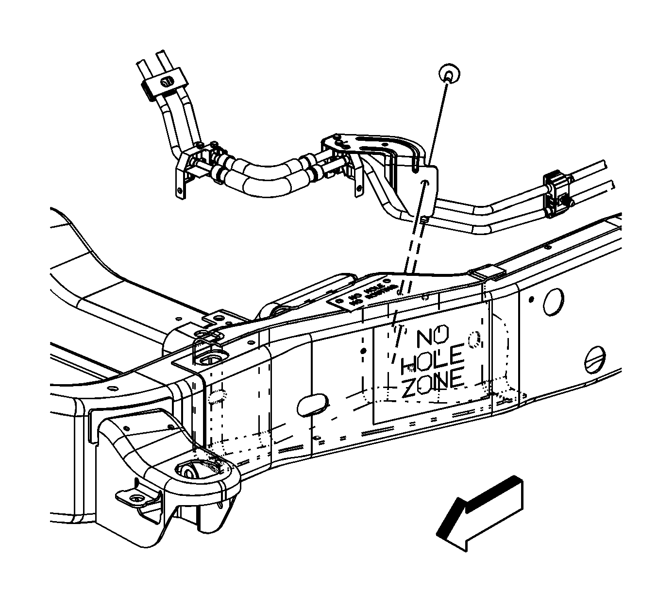
- Remove the fuel and EVAP line clips from the frame and brace.
- Remove the fuel/EVAP line bundle.
Installation Procedure
- Install the fuel/EVAP line bundle.
- Install the fuel and EVAP line clips to the frame and brace.
- Remove the caps from the fuel and EVAP lines at the fuel tank.
- Connect the fuel feed and EVAP lines to the fuel tank lines. Refer to Plastic Collar Quick Connect Fitting Service .
- Install the fuel line bracket bolt.
- If equipped with 4WD, install the fuel hose/pipe clip to the bracket on the transfer case.
- Install the fuel line clip to the bracket on the automatic transmission.
- Install the fuel pipe bracket to the bellhousing stud.
- Install the fuel pipe bracket nut.
- Reposition and install the front propeller shaft bolts. Refer to Front Propeller Shaft Replacement in Propeller Shaft.
- Lower the vehicle.
- Remove the caps from the fuel rail and EVAP line.
- Connect the EVAP canister purge line (2).
- Connect the fuel feed line (1) at the fuel rail. Refer to Metal Collar Quick Connect Fitting Service .
- Install the fuel fill cap.
- Connect the negative battery cable. Refer to Battery Negative Cable Disconnection and Connection in Engine Electrical.
- Use the following procedure in order to inspect for leaks:
Notice: Refer to Fastener Notice in the Preface section.
Tighten
Tighten the bolt to 12 N·m (106 lb in).
Tighten
Tighten the nut to 10 N·m (89 lb in).
| 17.1. | Turn the ignition ON, with the engine OFF, for 2 seconds. |
| 17.2. | Turn the ignition OFF for 10 seconds. |
| 17.3. | Turn the ignition ON, with the engine OFF. |
| 17.4. | Inspect for fuel leaks. |
Fuel Hose/Pipes Replacement - Chassis 2500 Series - Front
Removal Procedure
Important: Clean all fuel and evaporative emission (EVAP) line connections and surrounding areas prior to disconnecting the lines in order to avoid possible fuel and/or EVAP system contamination.
- Relieve the fuel system pressure. Refer to Fuel Pressure Relief .
- Disconnect the fuel feed pipe (1) at the fuel rail. Refer to Metal Collar Quick Connect Fitting Service .
- Disconnect the evaporative emission (EVAP) canister purge pipe (2). Refer to Plastic Collar Quick Connect Fitting Service .
- Cap the fuel rail and EVAP pipes.
- Raise and suitably support the vehicle. Refer to Lifting and Jacking the Vehicle in General Information.
- Remove the fuel pipe bracket nut.
- Remove the fuel pipe bracket from the bellhousing stud.
- Remove the fuel line clip from the bracket on the automatic transmission.
- If equipped with 4-wheel drive (4WD), remove the fuel hose/pipe clip from the bracket on the transfer case.
- Remove the front fuel tank. Refer to Fuel Tank Replacement .
- Remove the fuel line bracket nuts.
- Remove the fuel/EVAP line bundle.
Installation Procedure
- Install the fuel/EVAP line bundle.
- Install the fuel line bracket nuts.
- Install the front fuel tank. Refer to Fuel Tank Replacement .
- If equipped with 4WD, install the fuel hose/pipe clip to the bracket on the transfer case.
- Install the fuel line clip to the bracket on the automatic transmission.
- Install the fuel pipe bracket to the bellhousing stud.
- Install the fuel pipe bracket nut.
- Lower the vehicle.
- Remove the caps from the fuel rail and EVAP pipe.
- Connect the EVAP canister purge pipe (2). Refer to Plastic Collar Quick Connect Fitting Service .
- Connect the fuel feed line (1) to the fuel rail. Refer to Metal Collar Quick Connect Fitting Service .
- Install the fuel fill cap.
- Connect the negative battery cable. Refer to Battery Negative Cable Disconnection and Connection in Engine Electrical.
- Use the following procedure in order to inspect for leaks:
Notice: Refer to Fastener Notice in the Preface section.
Tighten
Tighten the bolt to 12 N·m (106 lb in).
Tighten
Tighten the nut to 10 N·m (89 lb in).
| 14.1. | Turn the ignition ON, with the engine OFF, for 2 seconds. |
| 14.2. | Turn the ignition OFF for 10 seconds. |
| 14.3. | Turn the ignition ON, with the engine OFF. |
| 14.4. | Inspect for fuel leaks. |
