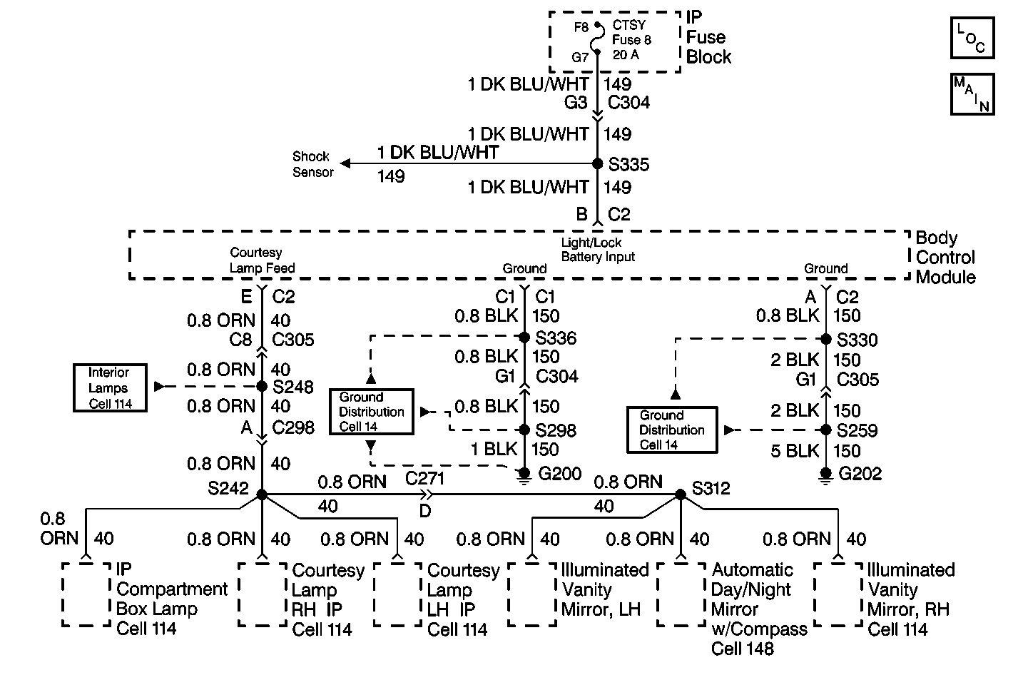
Circuit Description
The body control module (BCM) provides a voltage for the courtesy lamps when commanded by one of the following components:
| • | The instrument panel (IP) dimmer switch |
| • | The left door jamb switch |
| • | The right door jamb switch |
| • | The left rear door jamb switch |
| • | The right rear door jamb switch |
| • | The cargo door jamb switch input |
| • | The liftgate jamb switch |
S248 distributes power to the following:
| • | The dome lamp |
| • | The courtesy/reading lamps |
| • | IP compartment box lamp |
| • | Illuminated vanity mirrors |
| • | automatic day/night mirror |
Conditions for Setting the DTC
| • | CKT 157 is shorted to battery. |
| • | CKT 156 (courtesy lamps feed) is shorted to the battery for greater than 50 milliseconds, while the BCM is attempting to ground this circuit. |
Action Taken When the DTC Sets
| • | DTC 22 will set. |
| • | There will be no courtesy lighting in the vehicle. |
| • | The BCM will read out a series of flash DTCs upon entering diagnostic mode. |
Conditions for Clearing the MIL/DTC
The fault is corrected and the DTC memory is cleared.
Diagnostic Aids
If the only DTC that flashes is a history code (DTC 32), the problem may be intermittent. Try performing the test shown while "wiggling" wiring and connectors. This action can often cause the fault to appear. Test for poor connections at the BCM connector, which could cause an open or an intermittent fault. Refer to Intermittent/History DTCs.
Test Description
The number(s) below refer to the step number(s) on the diagnostic table.
-
This step tests for an open CTSY fuse 3.
-
If CTSY fuse 3 is open, this step tests for a short to the ground on CKT 149.
-
Prompts repair for a short to ground in CKT 149.
-
If CTSY fuse 3 is OK, this step tests for voltage output from the BCM in CKT 40.
-
This step tests for open in CKT 40.
-
Prompts replacement of the BCM.
Important: Inspect for the proper installation of aftermarket electronic equipment which may affect the integrity of the system.
Step | Action | Value(s) | Yes | No |
|---|---|---|---|---|
1 | Check CTSY Fuse 3. Is Fuse 3 open? | -- | Go to Step 2 | Go to Step 4 |
2 | Using a DMM check for continuity between connector C304 cavity G3 and ground Is continuity present? | -- | Go to Step 3 | Go to Step 6 |
3 | Repair short to ground in CKT 149 between IP fuse block and BCM connector C1 a cavity B. Is repair complete? | -- | System OK | -- |
4 | Using DMM check for voltage at connector C305 cavity C8. Is voltage present? | 12 volts | Go to Step 5 | Go to Step 6 |
5 | Check for an open in CKT 40 from BCM connector C2 cavity E to S248. Is repair complete? | -- | System OK | -- |
6 | Replace the BCM. Is the repair complete? | -- | System OK | -- |
