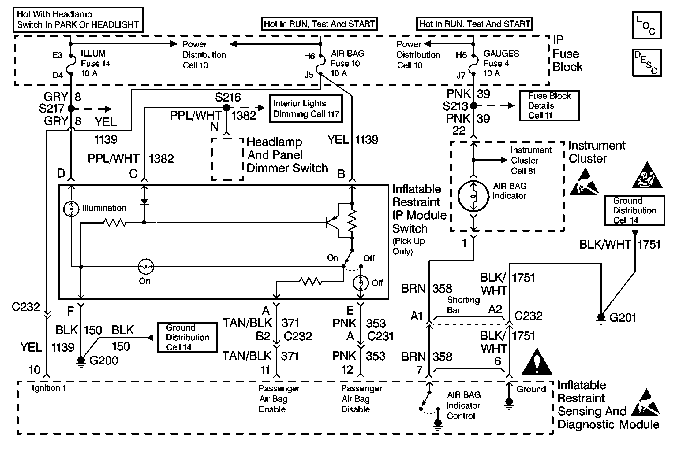
Circuit Description
In the RUN position, the ignition switch applies battery voltage to the AIR BAG warning lamp and to the IGNITION 1 input terminal 10. The inflatable restraint sensing and diagnostic module responds by flashing the AIR BAG warning lamp 7 times. The inflatable restraint sensing and diagnostic module monitors the voltage levels at the PASSENGER AIR BAG ENABLE terminal 11 and PASSENGER AIR BAG DISABLE terminal 12 of the inflatable restraint sensing and diagnostic module to determine the position of the inflatable restraint IP module switch.
Conditions for Setting the DTC
| • | The voltage detected at PASSENGER AIR BAG ENABLE terminal 11 and PASSENGER AIR BAG DISABLE terminal 12 are less than 1.0 volt when the AIR BAG ON lamp is commanded on. |
| • | The voltage detected at PASSENGER AIR BAG ENABLE terminal 11 and PASSENGER AIR BAG DISABLE terminal 12 are greater than 4.0 volts when the AIR BAG ON lamp is commanded OFF. |
| • | The voltage detected at PASSENGER AIR BAG ENABLE terminal 11 and PASSENGER AIR BAG DISABLE terminal 12 are greater than 1.0 volt when the AIR BAG OFF lamp is commanded ON. |
Action Taken When the DTC Sets
| • | The inflatable restraint sensing and diagnostic module (SDM) attempts to illuminate the AIR BAG OFF lamp. |
| • | The inflatable restraint IP module switch is defaulted to the disabled state. |
| • | The SDM sets a diagnostic trouble code. |
| • | The SDM turns ON the AIR BAG warning lamp. |
Conditions for Clearing the DTC
| • | Current DTC: The voltage at PASSENGER AIR BAG ENABLE terminal 11 is greater than 4.0 volts for 500 milliseconds and the voltage at PASSENGER AIR BAG DISABLE terminal 12 is less than 1.0 volts for 500 milliseconds when the AIR BAG ON lamp is commanded ON. |
| • | History DTC: |
| - | You issue a scan tool CLEAR CODES command. |
| - | After 250 malfunction free ignition cycles have occurred |
Diagnostic Aids
Refer to AIR BAG Warning Lamp Comes On Steady and AIR BAG Warning Lamp Does Not Come On to diagnose warning lamp circuit malfunctions.
When measurements are requested in this table, use the J 39200 DMM with the correct terminal adapter from the J 35616 Connector Test Adapter Kit. When an inspection for proper connection is requested, refer to Testing for Electrical Intermittents in Wiring Systems. When a wire, connector or terminal repair is requested, use the J-38125 Terminal Repair Kit and refer to Wiring Repairs in Wiring Systems.
Test Description
The number(s) below refer to the step number(s) on the diagnostic table.
-
This test determines if the correct voltage is being supplied to the SDM terminal 11 on CKT 371. When the IP switch is in the ON position the voltage should read HIGH on the scan tool. This also indicates a good 1139 circuit. A reading of LOW indicates either an open, high resistance, or ground in CKT 371 or CKT 1139.
-
This test determines if the IP switch is receiving power on CKT 1139 and ground on CKT 150.
-
This test isolates a bad IP switch from a bad ground through CKT 150. Since the passenger air bag enable is HIGH the IP switch is receiving power on CKT 1139.
-
This test determines if the correct voltage is being supplied to the SDM terminal 12 on CKT 353. When the IP switch is in the ON position the voltage should read LOW. If the reading is HIGH a short to B+ on CKT 353 is indicated.
-
This test determines if the correct voltage is being supplied to the SDM terminal 12 on CKT 353. When the IP switch is in the OFF position the voltage should read HIGH. After a brief delay, the SDM grounds the circuit in order to illuminate the air bag OFF lamp which causes the voltage to read LOW. If the voltage does not respond properly, an open, high resistance or grounded CKT 353, or a short to B+ on CKT 371 or a SDM unable to control the air bag OFF lamp is indicated. Diagnose a short to B+ on CKT 353 on this step.
-
This test determines if the correct voltage is being supplied to the SDM terminal 11 on CKT 371. The voltage reads LOW when the IP switch is in the OFF position. If the reading is high a short to B+ is indicated on CKT 371.
-
This test determines if the SDM passenger air bag OFF lamp driver command is being issued in an attempt to ground CKT 353. If the command is correct, an open of CKT 353 exists. If the command is not being issued, a short to B+ on CKT 371 or a faulty SDM is indicated.
-
This test determines if the correct voltage is being supplied to the SDM terminal 11 on CKT 371. When the IP switch is in the OFF position the voltage should read LOW. A HIGH reading indicates a short to B+ on CKT 371 which would prevent the SDM from attempting to control the air bag OFF lamp.
-
This test determines if a short to voltage exists on CKT 353. If CKT 353 is not shorted to B+, either a short to B+ on CKT 371 or a faulty SDM is indicated.
-
This test determines if a short to voltage on CKT 353 is caused by a defective IP switch assembly or a wiring problem.
-
This test determines if the correct voltage is being supplied to the SDM terminal 11 on CKT 371. When the IP switch is in the OFF position the voltage should read LOW. A HIGH reading indicated a short to B+ on CKT 371. A normal reading indicates a faulty SDM.
-
This test determines if a short to voltage on CKT 371 is caused by a defective IP switch assembly or a wiring problem.
-
This test determines if the correct voltage is being supplied to the SDM of terminal B CKT 17. IF CKT 1139 is receiving system voltage, when the IP switch is in the OFF position the voltage should read HIGH on CKT 353. After a brief delay, the SDM then grounds the circuit in order to illuminate the air bag OFF lamp which causes the voltage to read LOW.
-
This test determines if the correct voltage is being supplied to the SDM terminal 11 on CKT 371. When the IP switch is in the ON position the voltage should read approximately battery voltage. A low reading indicated an open, high resistance, or a short to ground on CKT 371. A normal reading would indicate a faulty SDM.
-
This test determines if a CKT 371 problem is caused by a defective IP switch assembly or a wiring problem.
-
This test determines if the correct voltage is being supplied to the IP switch terminal B on CKT 1139. This will isolate a faulty IP switch from a wiring problem.
-
This test determines if the correct voltage is being supplied to the SDM terminal 12 on CKT 353. When the IP switch is in the OFF position the voltage should read approximately battery voltage. If the voltage is low, an open, high resistance, or short to ground is indicated on CKT 353. If the voltage is normal a faulty SDM is indicated.
-
This test determines if a CKT 353 problem is caused by a defective IP switch assembly or a wiring problem.
-
This test determines if the SDM passenger air bag OFF lamp driver command is being issued in an attempt to ground CKT 353. Step 22 is only performed if the system has tested OK up to this point. If DTC B1054 is stored as current and the system is testing OK, a faulty SDM is indicated.
-
A faulty connection caused by loose, damaged, or corroded terminals at the SDM could cause incorrect monitoring or control of the IP switch circuits by the SDM.
-
A wiring problem has been diagnosed. The SIR system requires special wiring repair procedures due to the sensitive nature of the circuitry. Proper service procedures are essential. Refer to Wiring Repair for instructions.
-
A faulty IP switch assembly has been diagnosed.
Step | Action | Value(s) | Yes | No |
|---|---|---|---|---|
1 | Was the SIR Diagnostic System Check performed? | -- | Go to Step 2 | |
Does the passenger air bag enable parameter show the specified value? | HIGH | Go to Step 3 |
Go to Step 16 | |
Note the air bag ON indicator lamp on the inflatable restraint IP module enable/disable switch assembly. Is the air bag ON indicator lamp illuminated? | -- | Go to Step 5 | Go to Step 4 | |
Was a problem found? | -- | Go to Step 25 | Go to Step 26 | |
Does the passenger air bag disable parameter show the specified value? | LOW | Go to Step 6 | Go to Step 10 | |
Does the passenger air bag disable parameter show the specified value? | High for about one second then LOW | Go to Step 7 | Go to Step 8 | |
Does the passenger air bag disable parameter show the specified value? | LOW | Go to Step 22 | Go to Step 13 | |
Does the suppression lamp driver parameter show the specified value? | OFF for about one second then ON | Go to Step 20 | Go to Step 9 | |
Does the passenger air bag enable parameter show the specified value? | LOW | Go to Step 13 | ||
Is the voltage greater than the specified value? | 0 volts | Go to Step 11 | Go to Step 13 | |
Is the voltage greater than the specified value? | 0 volts | Go to Step 12 | Go to Step 26 | |
12 | Inspect CKT 353 for a short to ground. Was a problem found? | -- | Go to Step 25 | -- |
Is the voltage greater than the specified value? | 0 volts | Go to Step 14 | Go to Step 23 | |
Is the voltage greater than the specified value? | 0 volts | Go to Step 15 | Go to Step 26 | |
15 | Inspect CKT 371 for a short to voltage. Was a problem found? | -- | Go to Step 25 | -- |
Does the passenger air bag disable parameter show the specified value? | HIGH for approximately one second | Go Step 17 | Go to Step 19 | |
17 |
Is the voltage less than the specified value? | Near B+ System volts | Go to Step 18 | Go to Step 22 |
Was a problem found? | -- | Go to Step 25 | Go to Step 26 | |
Was a problem found? | -- | Go to Step 25 | Go to Step 26 | |
Is the voltage greater than the specified value? | 0 volts | Go to Step 23 | Go to Step 21 | |
Was a problem found? | -- | Go to Step 25 | Go to Step 26 | |
Does the suppression lamp driver parameter show the specified value? | OFF for about one second then ON | Go to Step 23 | ||
Inspect for high resistance caused by loose, damaged or corroded terminals or connections at the SDM. Was problem found? | -- | Go to Step 24 | ||
24 | Replace the harness connector at the SDM and the SDM as necessary. Refer to Wiring Repair. Is the repair complete? | -- | Go to Step 27 | -- |
Repair the vehicle wiring as indicated. Refer to Wiring Repair for specific instructions for repair or replacement of SIR Connectors (Plastic Body and Terminal Metal Pin), SIR Wire Pigtail Repair, and SIR Wire Repair. Is the repair complete? | -- | Go to Step 27 | -- | |
Has the inflatable restraint IP module enable/disable switch assembly been replaced? | -- | Go to Step 27 | -- | |
27 |
Have all the SIR components been reconnected and properly mounted? | -- | Go to Step 28 | -- |
28 | Clear all SIR DTC's (Diagnostic Trouble Codes). Have all SIR DTCs been cleared? | -- | -- |
