Removal Procedure
- Remove the instrument panel (I/P) trim panel. Refer to Instrument Panel Upper Trim Panel Replacement .
- Remove the center console, if equipped. Refer to Console Replacement .
- Disconnect the negative battery cable. Refer to Battery Negative Cable Disconnection and Connection in Engine Electrical.
- Remove the driver side knee bolster. Refer to Knee Bolster Replacement .
- Remove the lower I/P trim panel. Refer to Instrument Panel Lower Trim Panel Replacement .
- Remove the passenger side airbag module. Refer to Inflatable Restraint Instrument Panel Module Replacement in SIR.
- Remove the radio. Refer to Radio Replacement in Entertainment.
- Remove the HVAC control. Refer to HVAC Control Module Replacement in HVAC Systems - Automatic or HVAC Control Module Replacement in HVAC Systems - Manual.
- Remove the accessory switch housing. Refer to Accessory Switch Replacement .
- Remove the left air louver housing. Refer to Instrument Panel Outer Air Outlet Deflector Replacement - Left Side in Heating, Ventilation and Air Conditioning.
- Remove the steering column. Refer to Steering Column Replacement in Steering Wheel and Column.
- Remove the communication interface module (CIM), if equipped. Refer to Communication Interface Module Replacement in Cellular Communication.
- Remove the data link connector from the I/P. Refer to Data Link Connector Replacement in Computer/Integrating Systems.
- Remove the park brake release lever from the I/P. Refer to Parking Brake Release Handle Assembly Replacement in Park Brake.
- Remove the instrument panel cluster (IPC). Refer to Instrument Cluster Replacement .
- Remove both front window air duct from the I/P assembly.
- Remove the harness from the I/P. Refer to Instrument Panel Electrical Center or Junction Block Replacement - Left Side and Instrument Panel Electrical Center or Junction Block Replacement - Right Side .
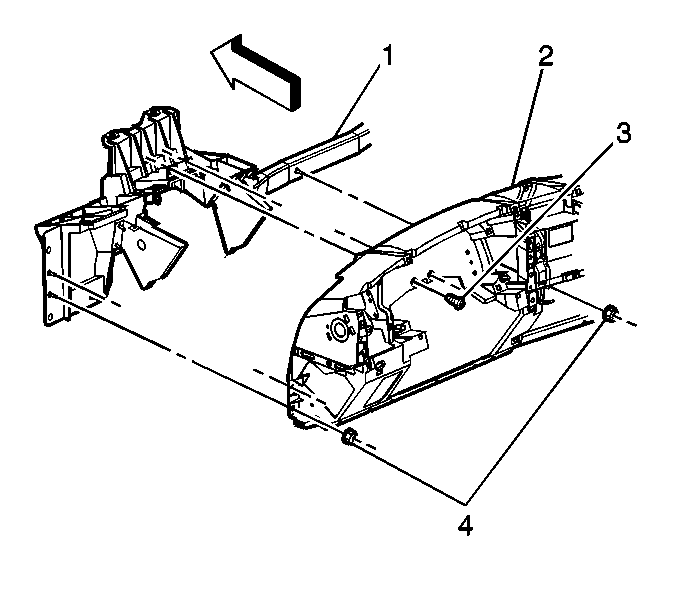
- Remove the I/P assembly retaining nuts (4) and bolts (3).
- Remove all harness hold down retainers from the I/P assembly.
- Remove the I/P assembly from the vehicle.
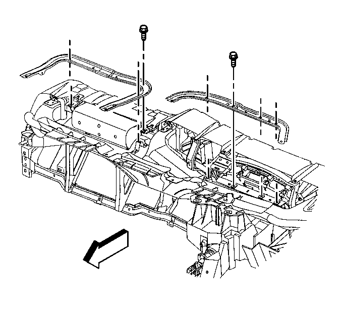
- Remove the I/P upper brackets.
- Disconnect all the electrical connectors from the wiring harness junction block. Refer to Body Wiring Harness Junction Block Replacement in Wiring Systems.
- Remove the transfer case control module from the bracket, if equipped. Refer to Transfer Case Shift Control Module Replacement in Transfer Case NVG 246-NP8.
- Remove the antenna cable from the cross car duct.
- Remove the cross car duct. Refer to Air Distributor Duct Replacement in Heating, Ventilation and Air Conditioning.
- Remove the amplifier, if equipped. Refer to Radio Speaker Amplifier Replacement in Entertainment.
- Separate the I/P harness from the carrier.
- If replacing the HVAC module, remove the right side of the carrier from the vehicle to gain access to the module.
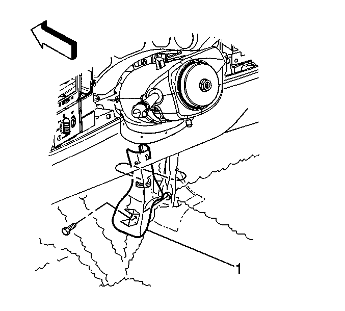
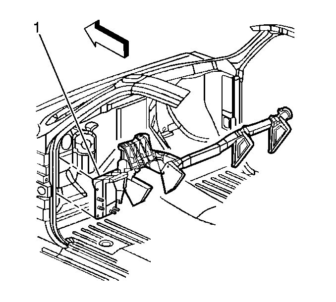
- Remove the I/P center support bracket bezel (1).
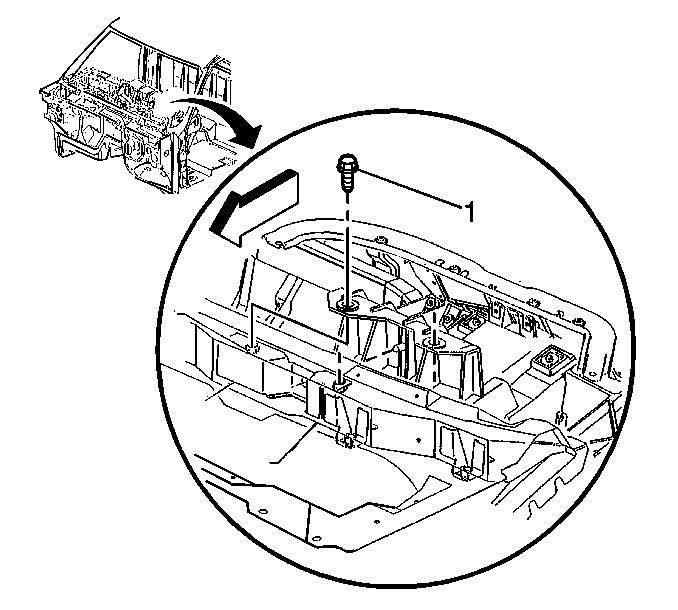
- Remove the I/P center support bracket bolt.
- Remove the I/P carrier retaining bolts.
- Remove the I/P carrier top bolts (1).
- Remove the I/P carrier (1) from the vehicle.
Caution: Refer to Battery Disconnect Caution in the Preface section.
Caution: Refer to SIR Caution in the Preface section.
Do not remove the I/P harness from the vehicle.
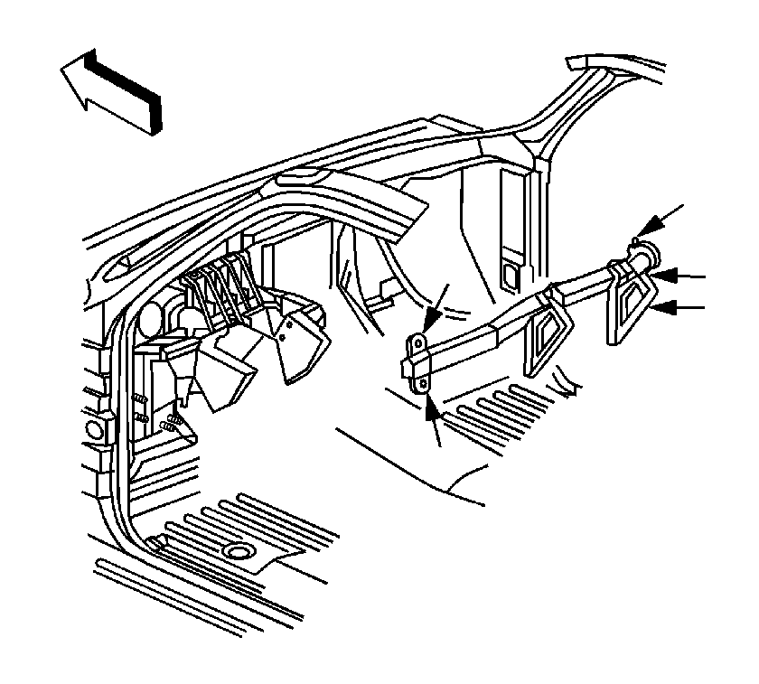
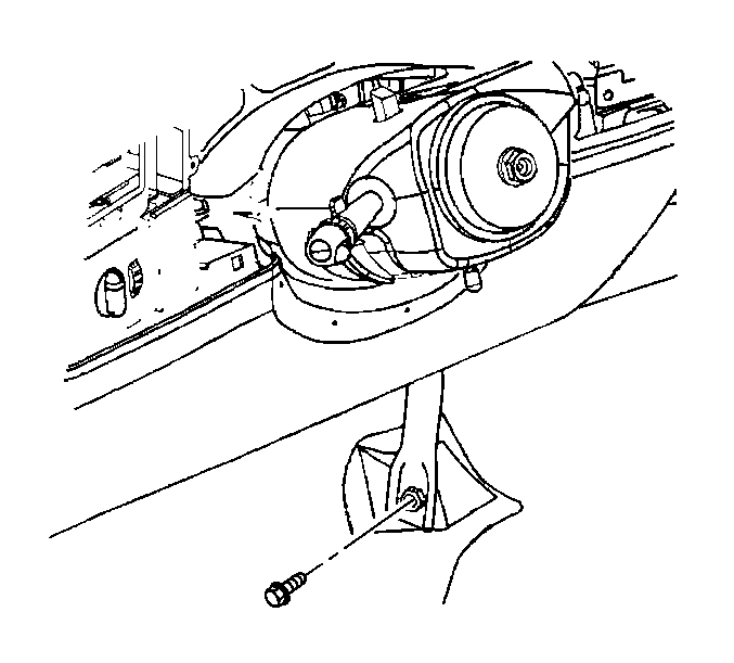
Important: Remove all of the parts of the I/P carrier assembly from the vehicle as a unit.
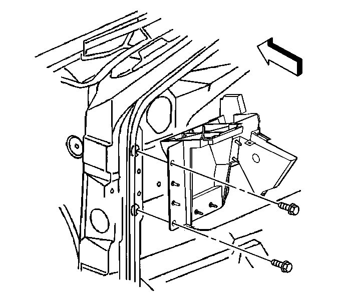
The left side is shown, the right side is similar.
Installation Procedure
- Position the I/P carrier (1) in the vehicle.
- Install the I/P carrier top bolts (1).
- Install the I/P carrier retaining bolts.
- Install the I/P center support bracket bolt.
- Install the I/P center support bracket bezel (1).
- Install the right side of the carrier to the vehicle, if the HVAC module was removed.
- Install the retaining bolts.
- Attach the I/P harness to the carrier.
- Install the amplifier, if equipped. Refer to Radio Speaker Amplifier Replacement in Entertainment.
- Install the cross car duct. Refer to Air Distributor Duct Replacement in Heating, Ventilation and Air Conditioning.
- Install the antenna cable to the cross car duct.
- Install the transfer case control module to the bracket, if equipped. Refer to Transfer Case Shift Control Module Replacement in Transfer Case NVG 246-NP8.
- Connect all of the electrical connectors to the wiring harness junction block. Refer to Body Wiring Harness Junction Block Replacement in Wiring Systems.
- Install the I/P upper brackets.
- Install the I/P assembly to the vehicle.
- Install the I/P assembly retaining bolts (3) and nuts (4).
- Install the harness hold down retainers to the I/P assembly.
- Install the harness to the I/P. Refer to Instrument Panel Electrical Center or Junction Block Replacement - Left Side and Instrument Panel Electrical Center or Junction Block Replacement - Right Side .
- Install both front window air duct to the I/P assembly.
- Install the IPC assembly. Refer to Instrument Cluster Replacement .
- Install the park brake release lever to the I/P. Refer to Parking Brake Release Handle Assembly Replacement in Park Brake.
- Install the data link connector to the I/P. Refer to Data Link Connector Replacement in Computer/Integrating Systems.
- Install the remote control door lock receiver module, if equipped. Refer to Remote Control Door Lock Receiver Replacement in Keyless Entry.
- Install the CIM, if equipped. Refer to Communication Interface Module Replacement in Cellular Communication.
- Install the steering column. Refer to Steering Column Replacement in Steering Wheel and Column.
- Install the left air louver housing. Refer to Instrument Panel Outer Air Outlet Deflector Replacement - Left Side in Heating, Ventilation and Air Conditioning.
- Install the accessory switch housing. Refer to Accessory Switch Replacement .
- Install the HVAC control. Refer to HVAC Control Module Replacement in HVAC Systems - Automatic or HVAC Control Module Replacement in HVAC Systems - Manual.
- Install the radio. Refer to Radio Replacement in Entertainment.
- Install the passenger side airbag module. Refer to Inflatable Restraint Instrument Panel Module Replacement in SIR.
- Install the lower trim panel. Refer to Instrument Panel Lower Trim Panel Replacement .
- Install the driver side knee bolster. Refer to Knee Bolster Replacement .
- Connect the negative battery cable. Refer to Battery Negative Cable Disconnection and Connection .
- Install the center console, if equipped. Refer to Console Replacement .
- Install the I/P trim panel. Refer to Instrument Panel Upper Trim Panel Replacement .

Notice: Refer to Fastener Notice in the Preface section.

Tighten
Tighten the bolts to 50 N·m (37 lb ft).

The left side is shown, the right is similar.
Tighten
Tighten the bolts to 50 N·m (37 lb ft).

Tighten
Tighten the bolt to 25 N·m (18 lb ft).


Tighten
Tighten the bolts to 50 N·m (37 lb ft).

Tighten
Tighten the retaining bolts to 2 N·m (18 lb in).

Ensure the wire harness is routed to all of the openings.
Tighten
Tighten the retaining bolts and nuts to 9 N·m (80 lb in).
