Tools Required
J 43218 Clamp Pliers Narrow Jaw
Removal Procedure
Important: Before disassembly, observe and accurately mark all of the driveline
components relative to the propeller shaft and to the axles. These items
include the following components:
• The propeller shafts • The wheel drive shafts • The pinion flanges • The output shafts
- Raise the vehicle. Refer to Lifting and Jacking the Vehicle in General Information.
- Remove the transfer case shield, if equipped. Refer to the appropriate procedure:
- Mark the relationship of the propeller shaft and of the front axle pinion yoke.
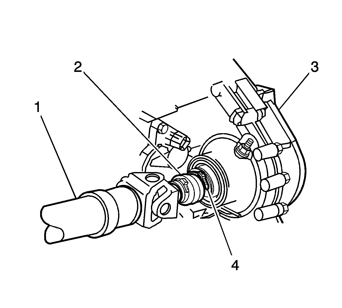
- Remove the clamp (4) at the transfer case (3) by prying up the exposed end of the clamp (4) with a flat-bladed tool.
- Remove the bolts (6) and the yoke retainers (7) from the front axle pinion yoke (1).
- Disconnect the propeller shaft (2) from the front axle pinion yoke (1).
- Remove the propeller shaft (5) from the transfer case output shaft by sliding the propeller shaft forward.
| • | Transfer Case Shield Replacement in Transfer Case - NVG 149-NP |
| • | Transfer Case Shield Replacement in Transfer Case - NVG 236/246-NP8 |
Notice: When removing the propeller shaft, do not attempt to remove the shaft by pounding on the yoke ears or using a tool between the yoke and the universal joint. If the propeller shaft is removed by using such means, the injection joints may fracture and lead to premature failure of the joint.
Wrap the bearing caps with tape in order to prevent the loss of bearing rollers.
Important: Do not drop the bearing cap assemblies of the yoke end.
Installation Procedure
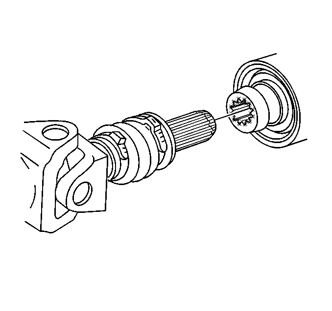
- Inspect the splines of the transfer case output shaft for a sufficient coating of lubricant. If the output shaft does not have a sufficient coating of lubricant, lubricate the shaft with lubricant GM P/N 12345879 (Canadian P/N 10953511) or with an equivalent lubricant meeting GM specification 9985830.
- Install the new clamp into the groove of the propeller shaft boot.
- Install the propeller shaft splines into the transfer case output shaft.
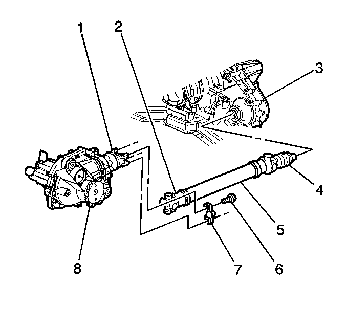
- Install the propeller shaft (5) to the front axle pinion yoke (1).
- Install the yoke retainers (7) and the bolts (6).
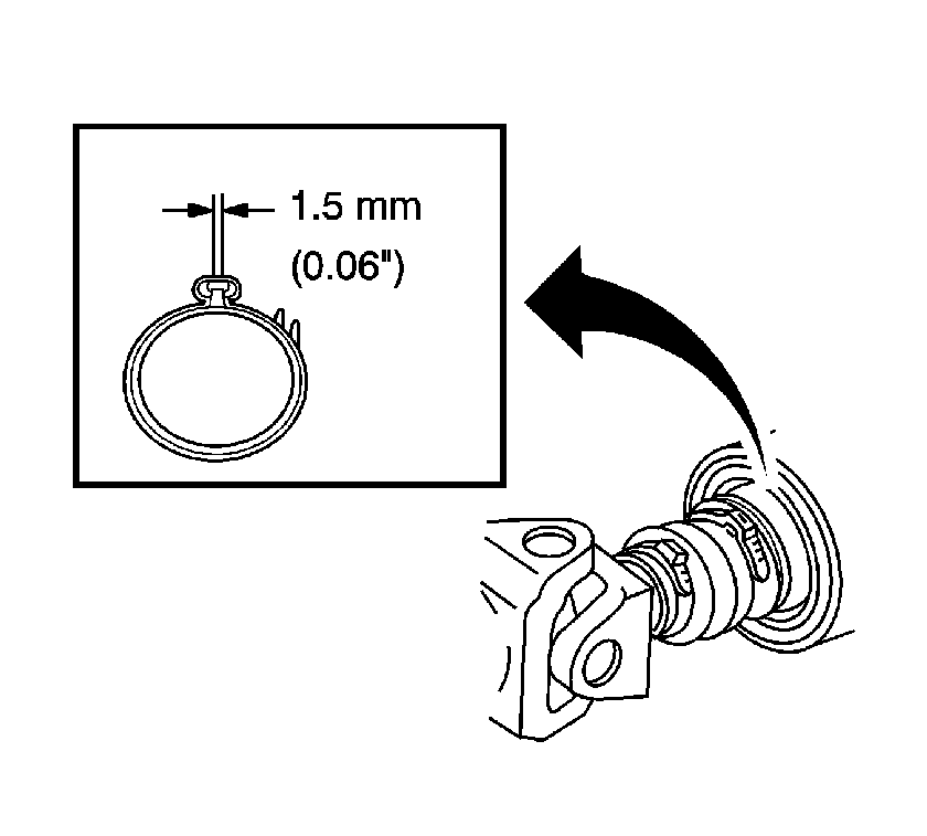
- Install the boot onto the transfer case output shaft until the boot is attached into the groove on the output shaft.
- Using the J 43218 , crimp the clamp until the dimensions that are shown are obtained.
- Install the transfer case shield, if equipped. Refer to the appropriate procedure:
- Lower the vehicle.
Align the reference marks that were made during removal.
Notice: Use the correct fastener in the correct location. Replacement fasteners must be the correct part number for that application. Fasteners requiring replacement or fasteners requiring the use of thread locking compound or sealant are identified in the service procedure. Do not use paints, lubricants, or corrosion inhibitors on fasteners or fastener joint surfaces unless specified. These coatings affect fastener torque and joint clamping force and may damage the fastener. Use the correct tightening sequence and specifications when installing fasteners in order to avoid damage to parts and systems.
Tighten
Tighten the yoke retainer bolts to 25 N·m (19 lb ft).
| • | Transfer Case Shield Replacement in Transfer Case - NVG 149-NP |
| • | Transfer Case Shield Replacement in Transfer Case - NVG 236/246-NP8 |
