For 1990-2009 cars only
Battery Positive Cable Replacement 12V Battery to Auxiliary BEC
Removal Procedure
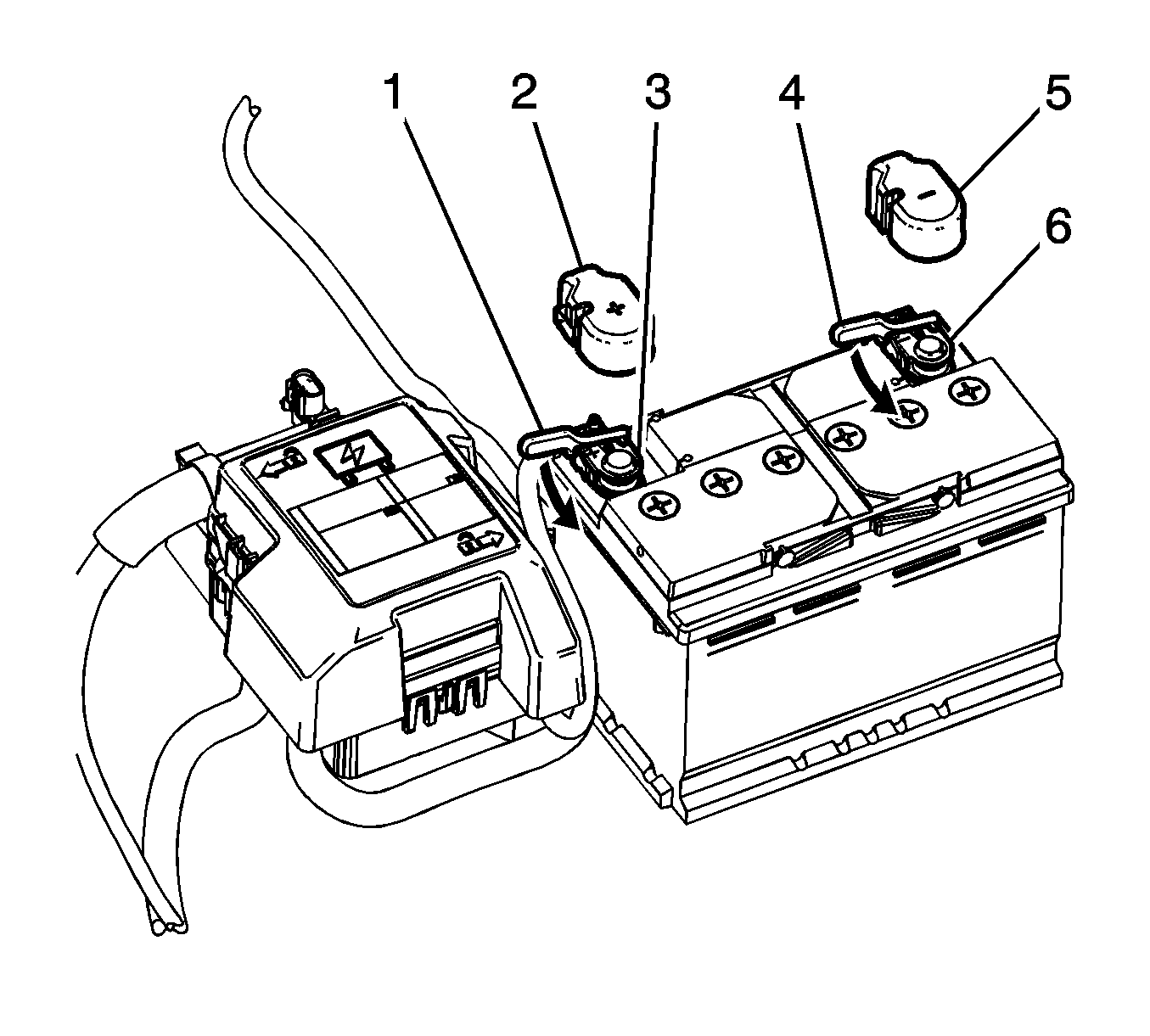
- Disconnect the negative battery cable. Refer to Battery Negative Cable Disconnection and Connection.
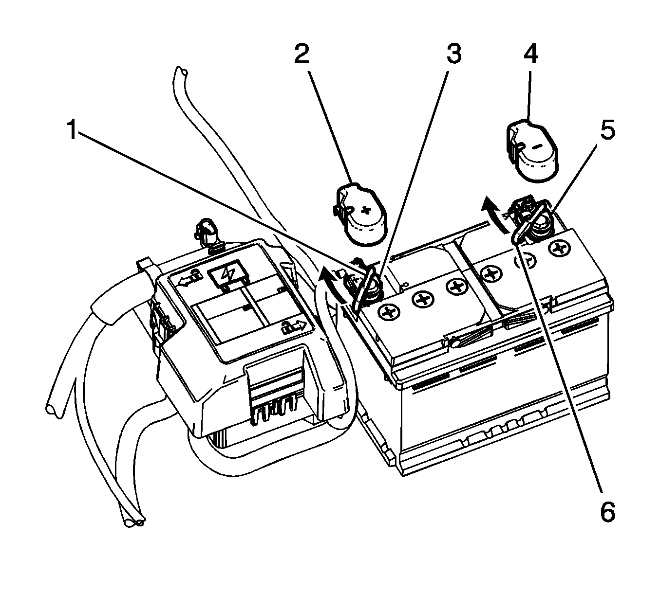
- Reposition the positive battery cable insulating cover (2) from over the positive terminal.
- Rotate the lever lock (1) counterclockwise in order to disconnect the positive battery cable.
- Remove the positive battery cable terminal (3) from the battery.
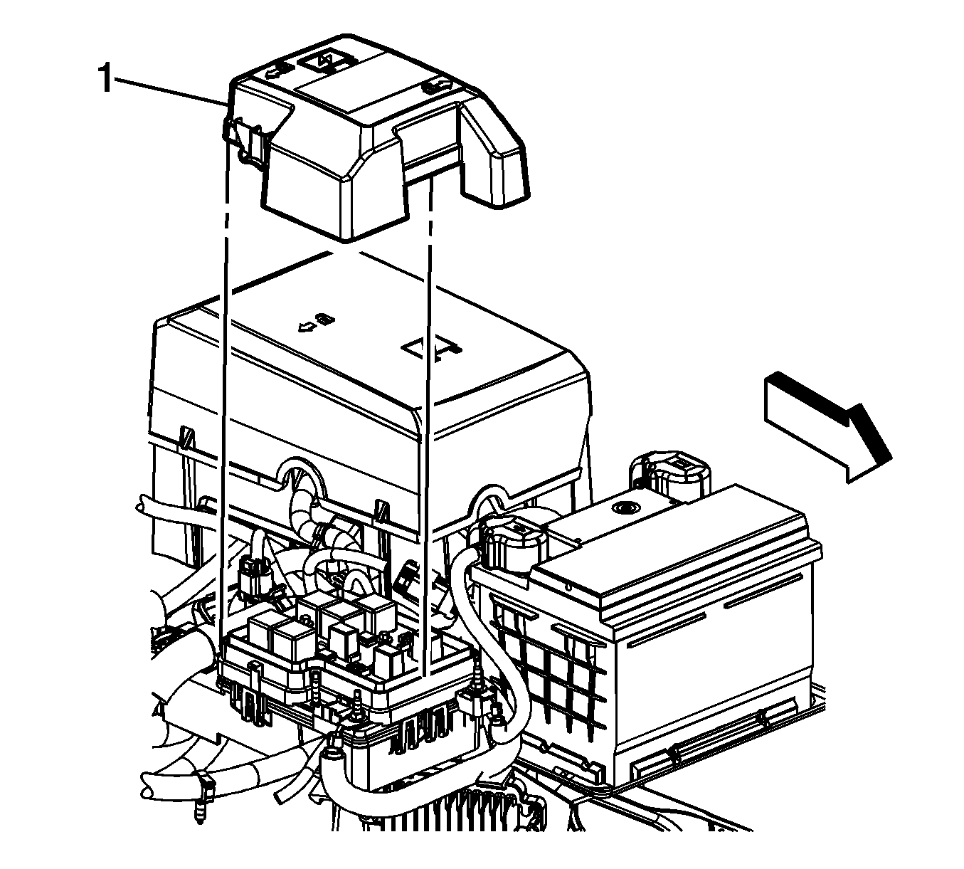
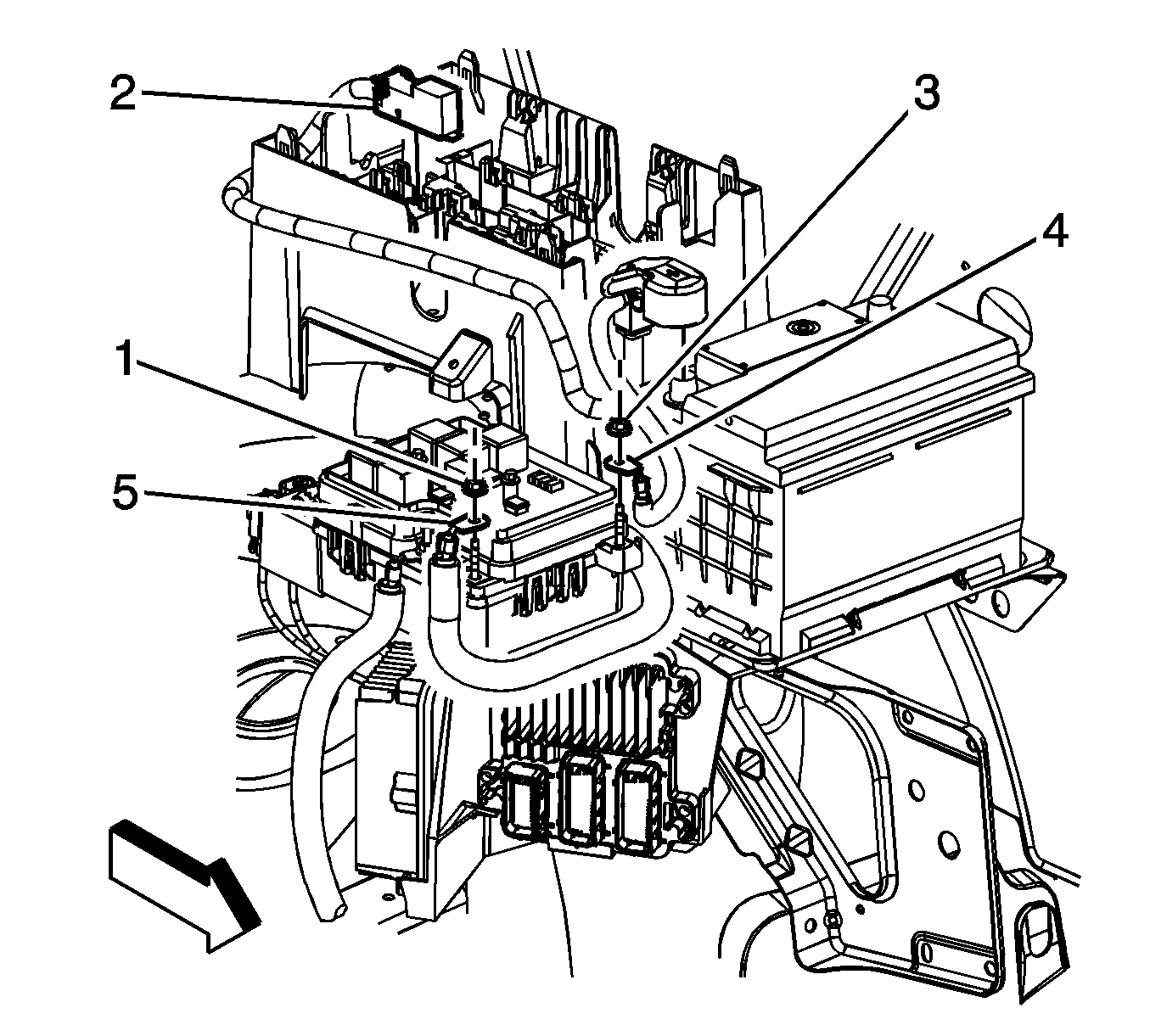
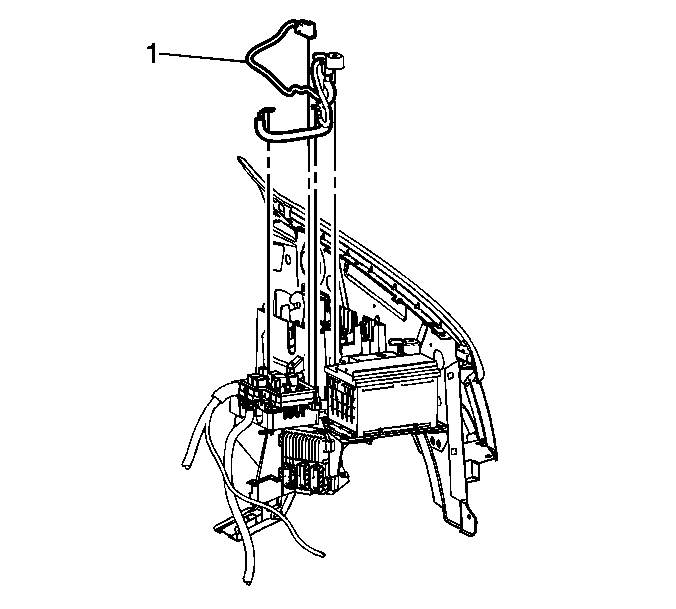
- Remove the auxiliary bussed electrical center (BEC) cover (1).
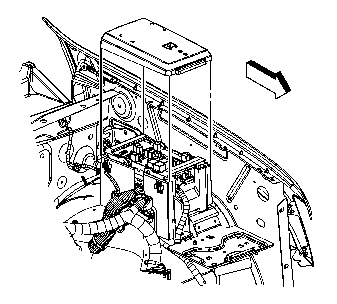
- Remove the underhood junction block cover.
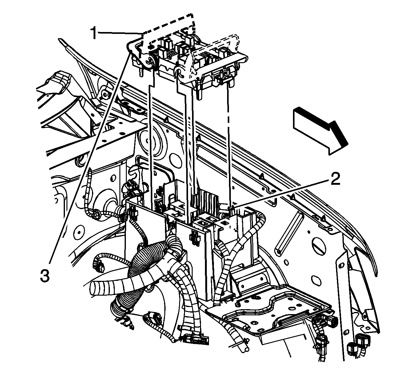
- Lift the junction block retainers from the locked position (3) and rotate the retainers to the open position (1).
- Remove the junction block.
- Remove the positive battery cable nut (1) from the mega fuse stud.
- Remove the positive battery cable nut (3) from the auxiliary BEC stud.
- Disconnect the positive battery cable connector (2) from the underhood BEC.
- Remove the positive battery cable assembly (1) from the vehicle.
Installation Procedure
- Install the positive battery cable assembly (1) to the vehicle.
- Install the positive battery cable leads to the mega fuse and auxiliary BEC studs.
- Connect the positive battery cable connector (2) to the underhood BEC.
- Install the positive battery cable nut (3) to the auxiliary BEC stud and tighten to 9 N·m (80 lb in).
- Install the positive battery cable nut (1) to the mega fuse stud and tighten to 9 N·m (80 lb in).
- Ensure that the junction block retainers are in the open position (1).
- Position and align the junction block to the 4 bracket pivots (2), once the pivots are engaged, push the retainers down into the locked position (3).
- Install the underhood junction block cover.
- Install the auxiliary BEC cover (1).
- Install the positive battery cable terminal (3) to the battery.
- Rotate the lever lock (1) clockwise until an audible click is heard in order to connect the positive battery cable.
- Position the positive battery cable insulating cover (2) over the positive terminal.
- Connect the negative battery cable. Refer to Battery Negative Cable Disconnection and Connection.
Caution: Refer to Fastener Caution in the Preface section.
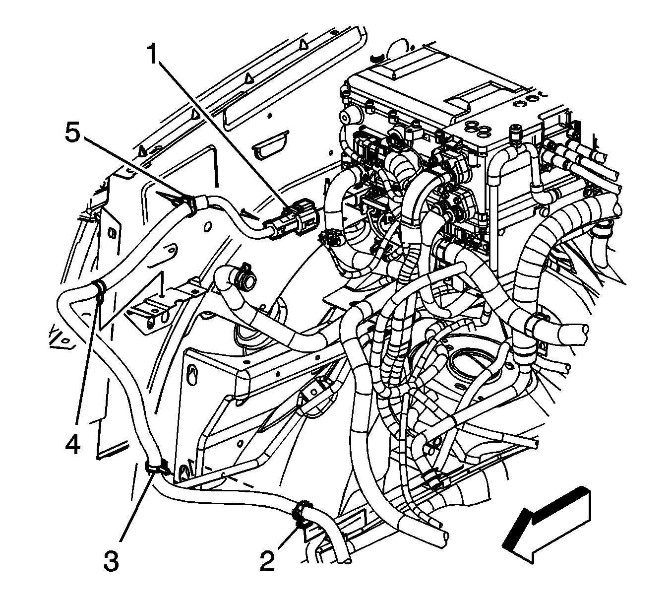
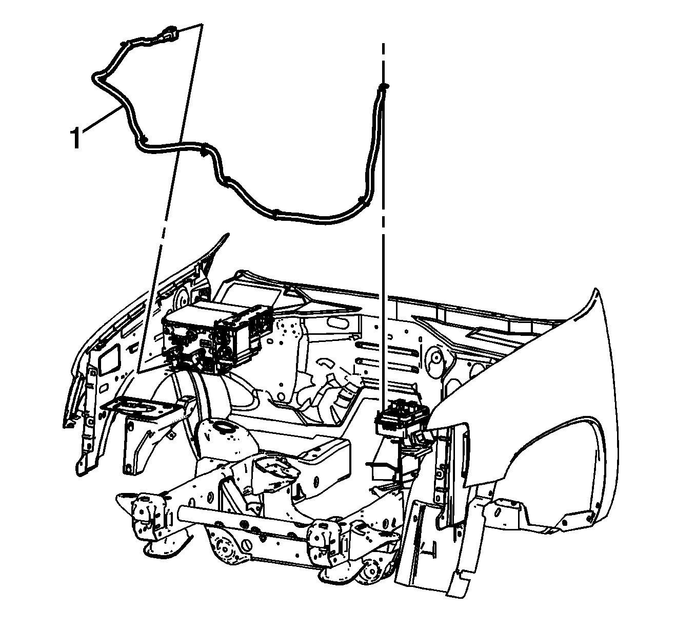
Battery Positive Cable Replacement Control Module to Auxiliary BEC
Removal Procedure
- Disable the high voltage system. Refer to High Voltage Disabling.
- Remove the auxiliary bussed electrical center (BEC) cover (1).
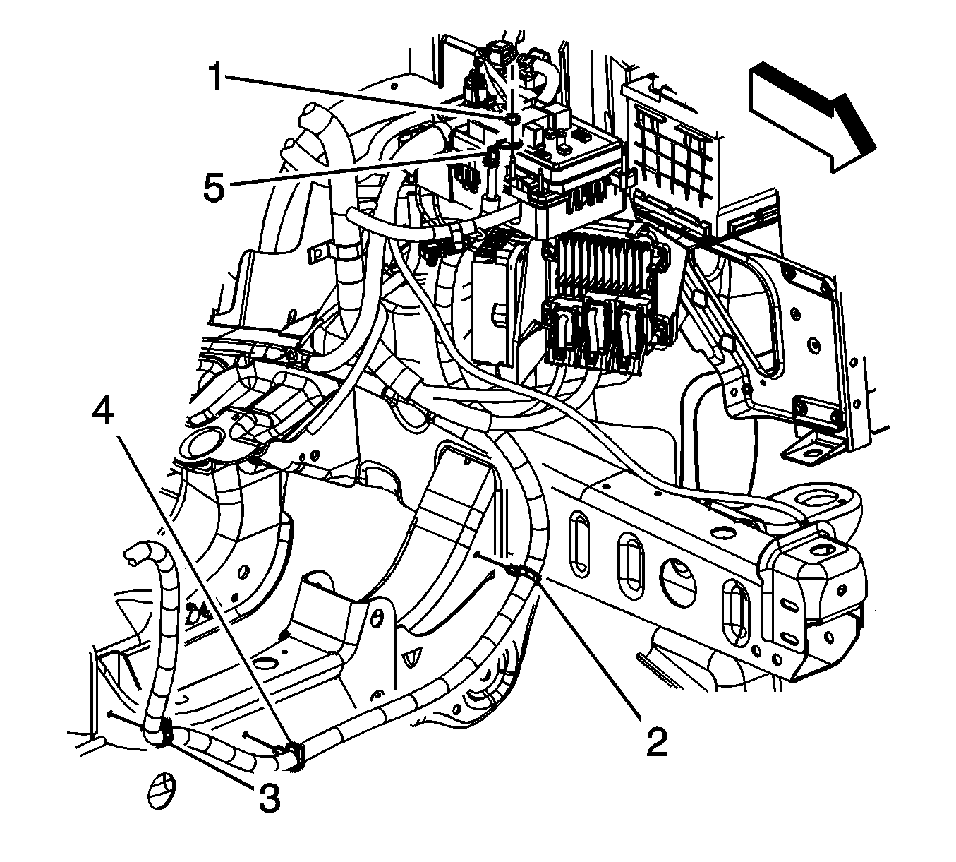
- Remove the positive battery cable nut (1) from the mega fuse stud.
- Remove the positive battery cable lead (5) from the mega fuse stud.
- Remove the engine shield. Refer to Engine Shield Replacement.
- Remove the positive battery cable clips (2, 3, and 4) from the frame crossmember.
- Lower the vehicle enough to remove the right wheelhouse panel. Refer to Wheelhouse Panel Replacement - Right Side.
- Working through the wheel opening, remove the positive battery cable clip (2) from the brake pipe.
- Working through the wheel opening, remove the positive battery cable clip (3) from the air cleaner adapter bracket
- Lower the vehicle.
- Remove the air cleaner assembly. Refer to Air Cleaner Assembly Replacement.
- Remove the positive battery cable clip (4) from the air cleaner support bracket.
- Remove the positive battery cable clip (5) from the fender inner panel.
- Disconnect the positive battery cable electrical connector (1) from the drive motor generator control module.
- Remove the positive battery cable (1) from the vehicle.
Installation Procedure
- Install the positive battery cable (1) to the vehicle.
- Connect the positive battery cable electrical connector (1) to the drive motor generator control module.
- Install the positive battery cable clip (5) to the fender inner panel.
- Install the positive battery cable clip (4) to the air cleaner support bracket.
- Install the air cleaner assembly. Refer to Air Cleaner Assembly Replacement.
- Raise and suitably support the vehicle enough to work through the wheel opening.
- Working through the wheel opening, install the positive battery cable clip (3) to air cleaner adapter bracket
- Working through the wheel opening, install the positive battery cable clip (2) to the brake pipe.
- Install the right wheelhouse panel. Refer to Wheelhouse Panel Replacement - Right Side.
- Fully raise the vehicle.
- Install the positive battery cable clips (2, 3, and 4) to the frame crossmember.
- Install the engine shield. Refer to Engine Shield Replacement.
- Lower the vehicle.
- Install the positive battery cable lead (5) to the mega fuse stud.
- Install the positive battery cable nut (1) to the mega fuse stud and tighten to 9 N·m (80 lb in).
- Install the auxiliary BEC cover (1).
- Enable the high voltage system. Refer to High Voltage Enabling.
Caution: Refer to Fastener Caution in the Preface section.
