Electronic Suspension Control Module Replacement Tahoe/Yukon/Escalade
Removal Procedure
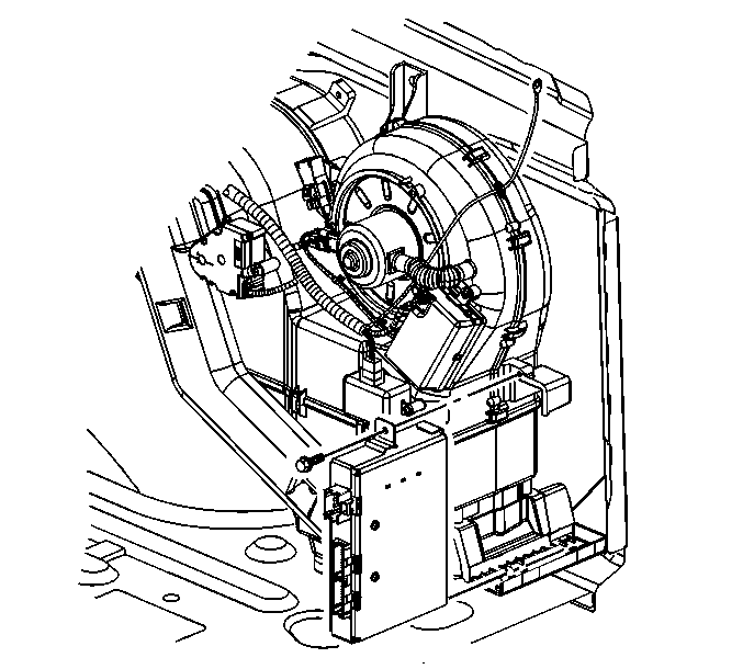
- Remove the right side interior trim panel. Refer to
Rear Quarter Trim Panel Replacement - Right Side
.

- Disconnect the electrical connectors from the module.
- Remove the screw.
- Slide the module from the bracket and remove the module from the vehicle.
Installation Procedure

- Install the module to the vehicle by sliding the module into the bracket.
Notice: Refer to Fastener Notice in the Preface section.
- Install the screw.
Tighten
Tighten the screw to 1.6 N·m (14 lb in).
- Connect the electrical connectors to the module.
Important:
| • | DO NOT program a control module unless you are directed by a service procedure or you are directed ay a General Motors Corporation service bulletin. Programming a control module at any other time will not permanently correct a customer's concern. |
| • | It is essential that the Tech 2 and the TIS terminal are both equipped with the latest software before performing the service programming system (SPS). |
| • | DTCs may set during programming. Clear DTCs after programming is complete. |
| • | Clearing DTCs will set the Inspection/Maintenance (I/M) system status indicators to NO. |
- If you are replacing the module, you must program the module. For step by step programming instructions, please refer to the techline information system (TIS) terminal. Refer to the following for additional programming and setup information.
Ensure the following conditions are met before programming a control module:
| - | There is not a charging system concern. All charging system concerns must be repaired before programming a control module. |
| - | Battery voltage is greater than 12 volts but less than 16 volts. The battery must be charged before programming the control module if the battery voltage is low. |
| - | The battery charger is NOT connected to the vehicle's battery. Incorrect system voltage or voltage fluctuations from a battery charger, may cause programming failure or control module damage. |
| - | Turn OFF or disable any system that may put a load on the vehicle's battery, such as the following components: |
| - | Daytime running lamps (DRL)--Applying the parking brake, on most vehicles, disables the DRL system. Refer to the Owner's Manual. |
| - | Heating, ventilation, and air conditioning (HVAC) systems |
| - | Engine cooling fans, radio, etc. |
| • | The ignition switch must be in the proper position. The Tech 2 prompts you to turn ON the ignition, with the engine OFF. DO NOT change the position of the ignition switch during the programming procedure, unless instructed to do so. |
| • | Make certain all tool connections are secure, including the following components and circuits: |
| - | The RS-232 communication cable port |
| - | The connection at the data link connector (DLC) |
| - | The voltage supply circuits |
| • | DO NOT disturb the tool harnesses while programming. If an interruption occurs during the programming procedure, programming failure or control module damage may occur. |
| • | DO NOT turn OFF the ignition if the programming procedure is interrupted or unsuccessful. Ensure that all control module and DLC connections are secure and the TIS terminal operating software is up to date. Attempt to reprogram the control module.
If the control module cannot be programmed, replace the control module. |
- If you are replacing the module you must also recalibrate the module by performing the following procedure:
| • | Connect the scan tool to the DLC. |
| • | Turn the ignition ON with the engine OFF. Select the SPECIAL FUNCTIONS for the RTD module on the scan tool. |
| • | Select the Recalibration line under SPECIAL FUNCTIONS and follow the instructions on the scan tool and techline terminal to complete the RTD module programming. |
| • | After completion of programming, return to SPECIAL FUNCTIONS on the scan tool, select ALC Trimset and follow the instructions displayed to perform the ALC trimset. |
| • | This applies to 15 series vehicles ONLY. |
- Install the right side interior trim panel. Refer to
Rear Quarter Trim Panel Replacement - Right Side
.
Electronic Suspension Control Module Replacement Escalade EXT
Removal Procedure

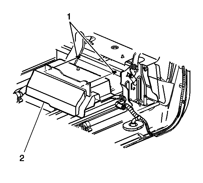
- Pull up on the handle at the rear of the seat to gain access to the control module.
- Remove the retainers (1) from the control module cover (2).

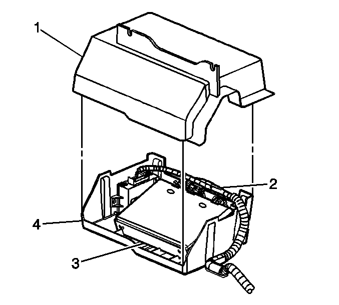
- Remove the cover (1) from the vehicle.
- Disconnect the wiring harness (2) from the control module (3).

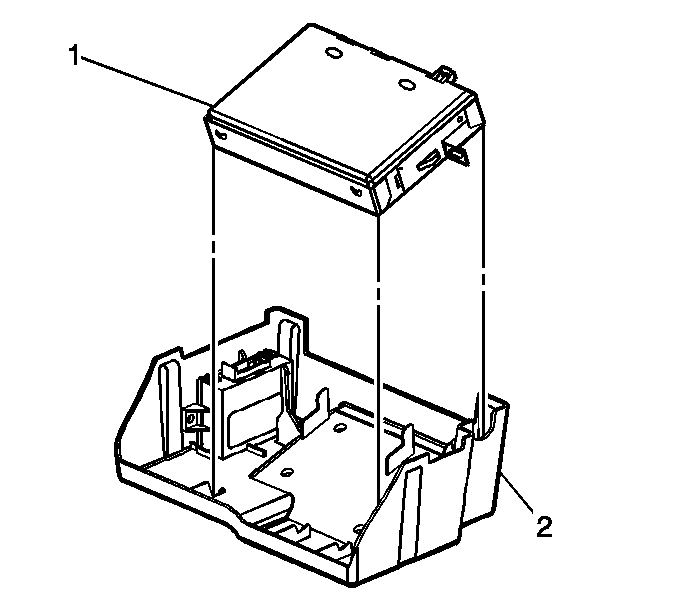
- Remove the control module (1) from the vehicle.
Installation Procedure

- Install the control module (1) to the vehicle.

- Connect the wiring harness (2) to the control module (3).
- If you are replacing the module, you must recalibrate the module. Refer to
Service Programming System (SPS) Description in Engine Controls - 4.8L, 5.3L, and 6.0L or
Service Programming System (SPS) Description in Engine Controls - 8.1L.
- After completion of programming, return to SPECIAL FUNCTIONS on the scan tool, select ALC Trimset and follow the instructions displayed to perform the ALC trimset.
This applies to 15 series vehicles ONLY.
- Install the cover (1) to the vehicle.

- Install the retainers (1) to the control module cover (2).
- Roll the seat downward in order to secure the seat in the original location.


