Differential Carrier Assembly Disassemble 9.25 Inch Axle
Tools Required
| • | J 29369-2
Bushing and Bearing Remover (2-3 in) |
| • | J 33791
Carrier Bushing Remover/Installer |
| • | J 36616
Axle Mount Bushing Remover/Installer |
| • | J 45754
Pinion Bearing Race Remover/Installer - 9.25 inch Axle |
Inspection Procedure
Perform the following before disassembling the axle:
- Remove the fill plug from the axle.
- Remove the drain plug from the axle.
- Drain the axle lubricant.
- Inspect the oil and the case for metal chips.
Determine the source of the metal chips, such as a broken gear or bearing cage.
- Check the ring gear backlash. Refer to
Backlash Inspection and Adjustment
.
This information can be used in order to determine the cause of the axle problem. The information will also help when setting up and preloading the differential case.
Determine the cause of the axle problem before disassembly, if possible.
Disassembly Procedure
- Remove the upper differential carrier assembly bushing
by performing the following steps:
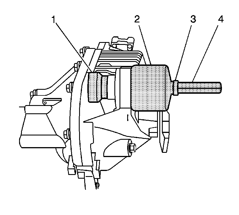
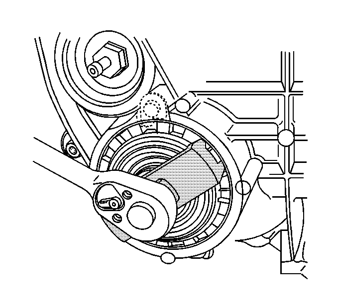
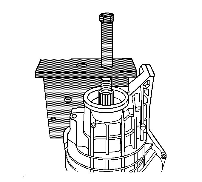
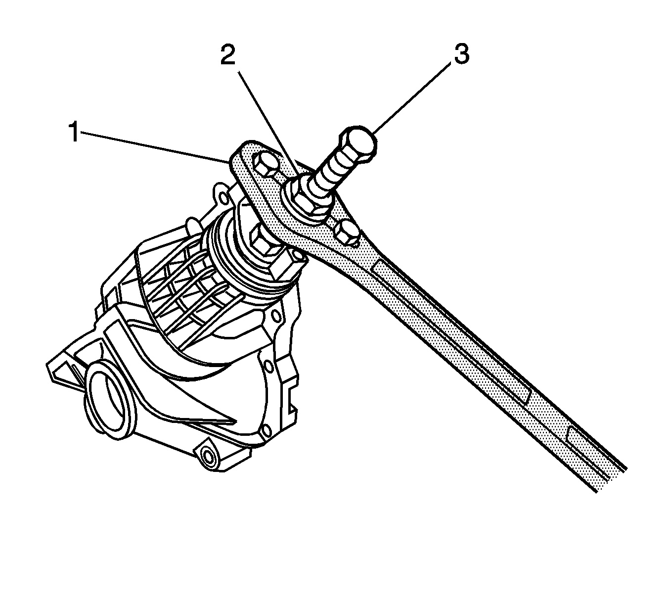
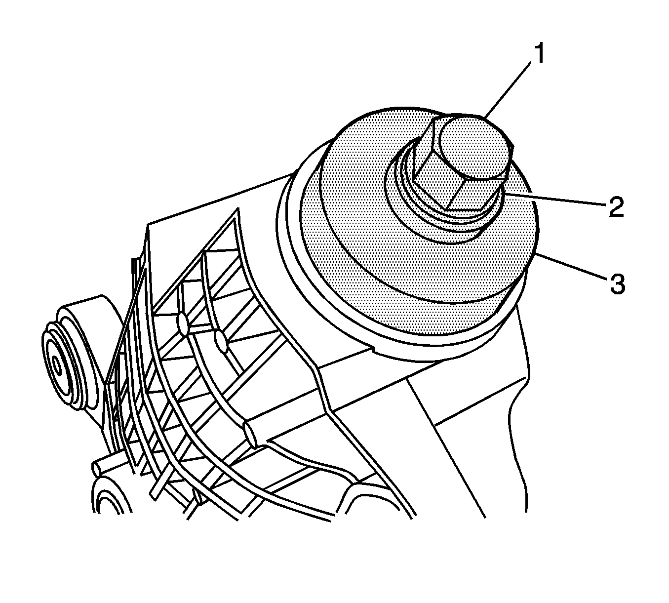
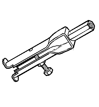
| 1.1. | Install the J 36616-2 (1), the J 33791-1 (2), the thrust bearing (3), the J 21474-18 (4), and the forcing screw as shown. |
| 1.2. | Remove the upper differential carrier assembly bushing by holding the forcing screw and tightening the J 21474-18. |
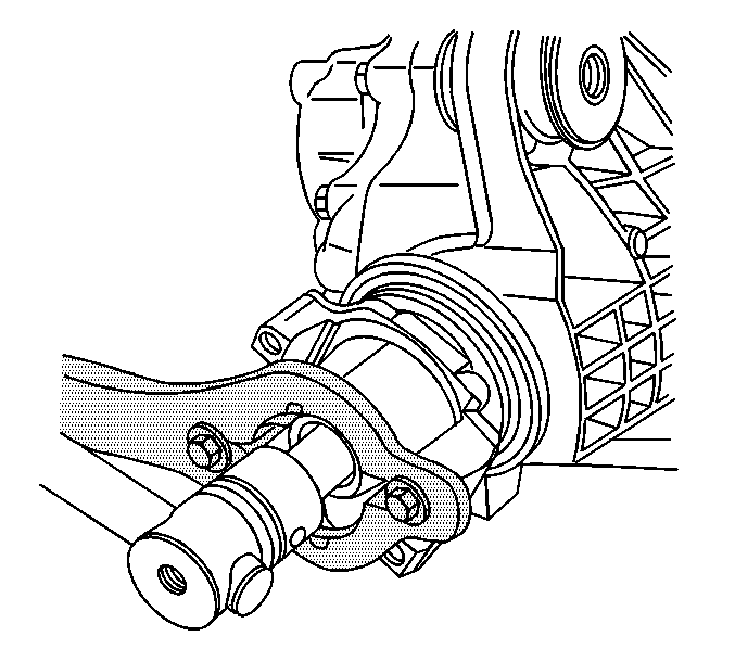
- Remove the lower differential carrier assembly bushing
by performing the following steps:
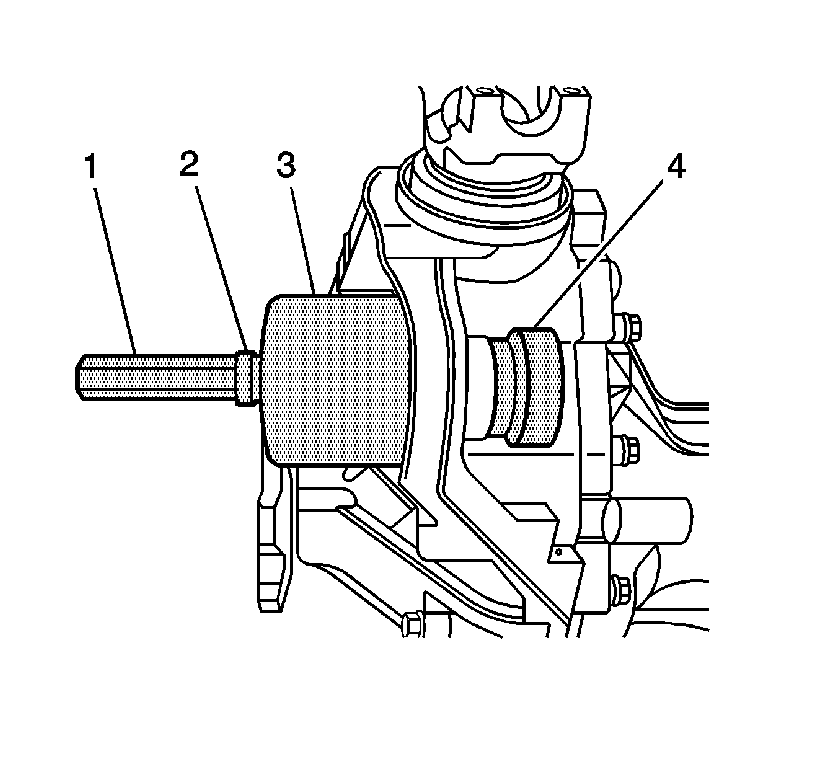
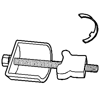
| 2.1. | Install the J 21474-18 (1), the thrust bearing (2), the J 33791-1 (3), the J 36616-2 (4), and the forcing screw as shown. |
| 2.2. | Remove the lower differential carrier assembly bushing by holding the forcing screw and tightening the J 21474-18. |
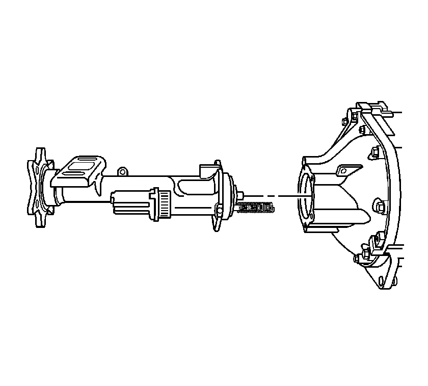
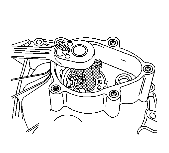
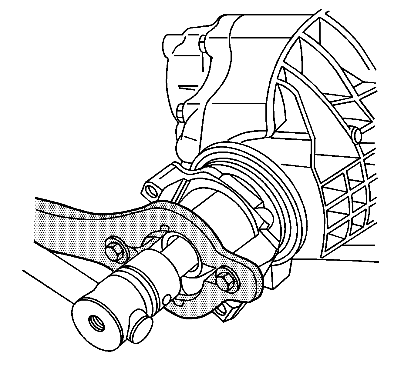
- Remove the front axle actuator.
- Remove the inner axle shaft housing to differential carrier assembly bolts.
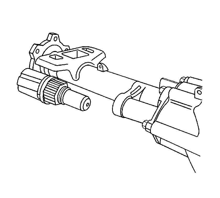
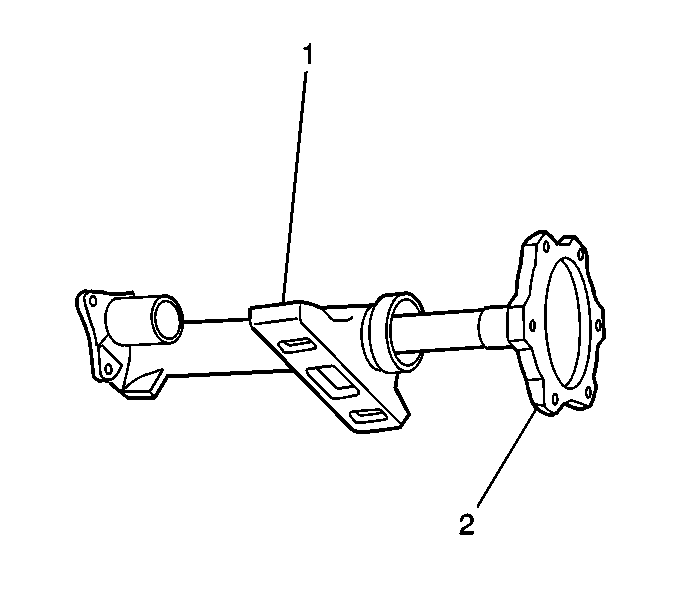
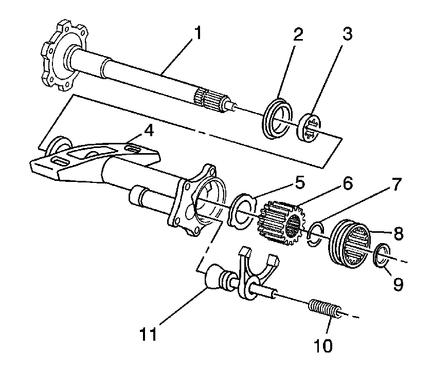
- Carefully remove the inner axle shaft
housing with the inner axle shaft and clutch fork components from the differential carrier assembly.
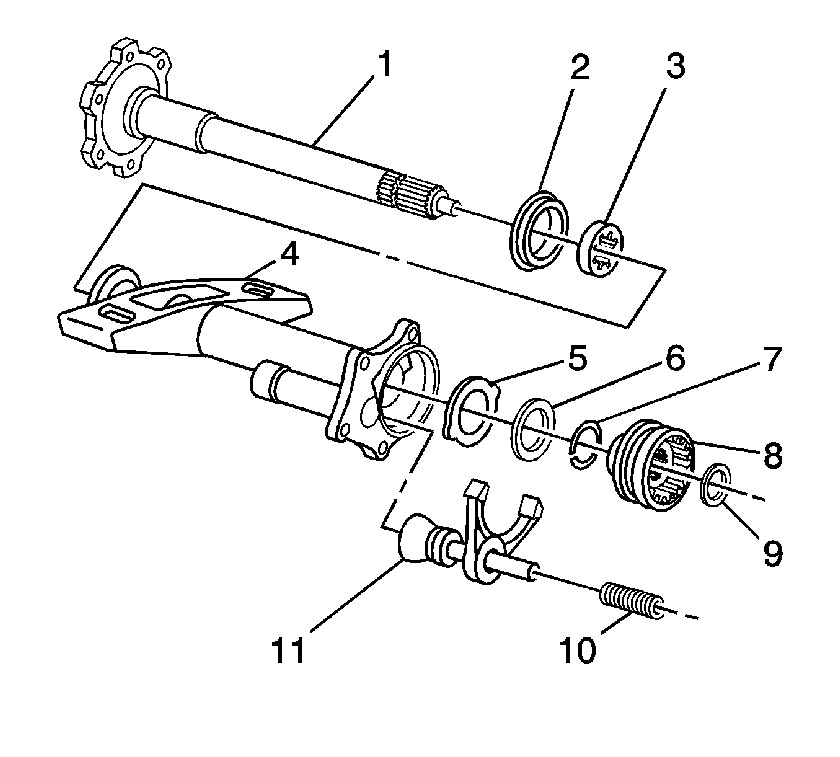
- Remove the following components from the inner axle
shaft housing (4):
| 6.1. | The clutch fork inner spring (10) |
| 6.2. | The clutch fork assembly (11) |
| 6.3. | The clutch shaft shim (9) |
| 6.4. | The clutch shaft sleeve (8) |
| 6.5. | The retainer ring (7) |
| 6.6. | The thrust washers (5, 6) |
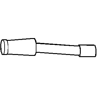
- Remove the inner axle shaft (2).
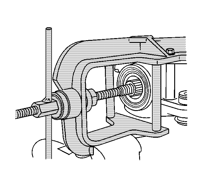
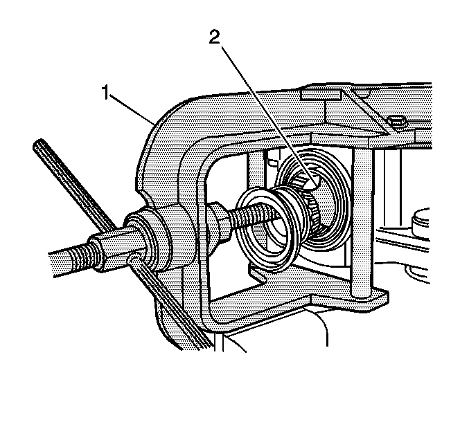
- Remove the inner axle shaft bearing and the inner axle shaft seal by performing
the following steps:
| 8.1. | Install the inner axle shaft housing into a vise. |
Clamp only on the mounting flange of the inner axle shaft housing.
| 8.2. | Install the
J 29369-2
(1) behind the inner axle shaft bearing. |
- Install the
J 2619-01
(2) to the
J 29369-2
(1).
- Remove the inner axle shaft bearing and the inner axle shaft bearing and the seal using the
J 2619-01
.
- Remove the inner axle shaft housing from the vise.
- Remove the front drive axle clutch shaft.
- Use the
J 34011
in order to
remove the clutch shaft bearing.
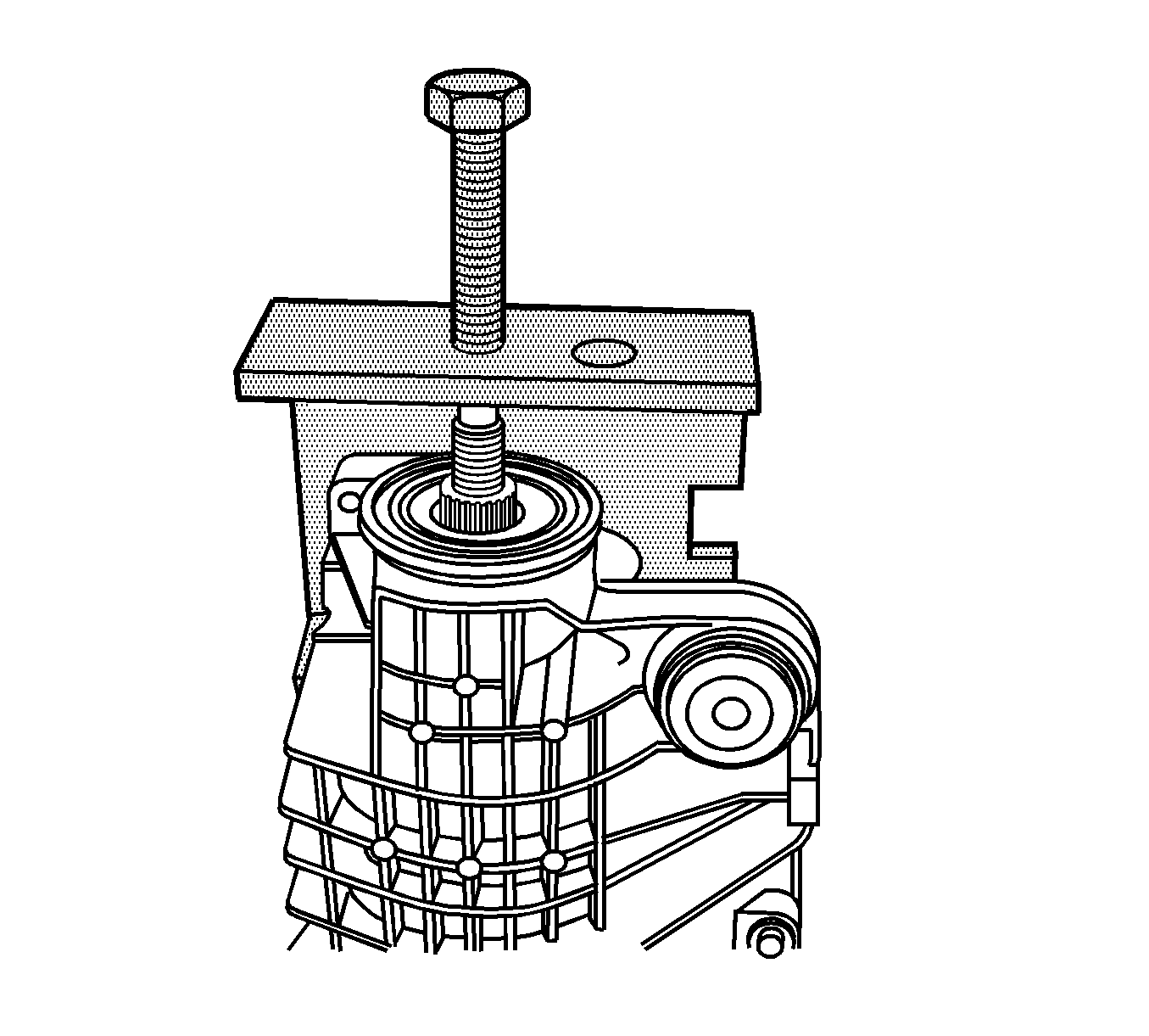
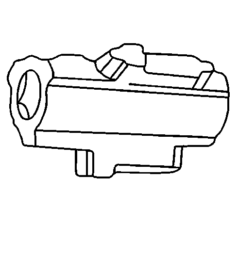
- Place the differential carrier assembly into a vise.
Clamp only on
the mounting flange of the differential carrier assembly case.
- Remove the inner axle shaft using a hammer and a brass drift.
- Install the
J 29369-2
(1) behind the inner axle shaft bearing.
- Install the
J 2619-01
(2) to the
J 29369-2
(1) .
- Remove the inner axle shaft bearing and the inner axle seal bearing and the seal using the
J 2619-01
.
- Remove the differential carrier assembly from the vise.
- Remove the vent connector.
- Remove the differential carrier assembly bolts.
- Separate the left carrier case half from the right carrier case half by tapping on the on the carrier case with a hammer and a brass drift.
- Remove the differential case assembly.
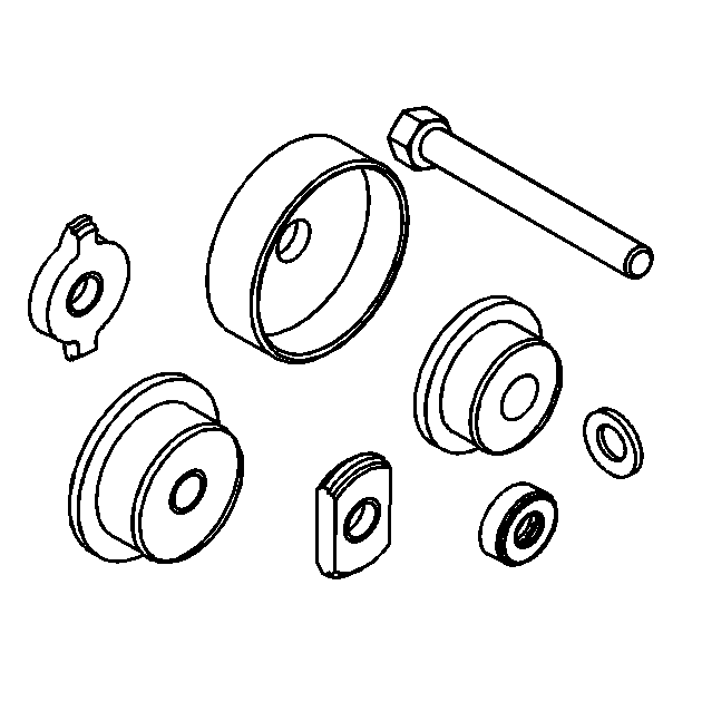
Disconnect the right side differential bearing adjuster nut lock from the differential bearing adjuster nut by prying up on the lock.
- Remove the left side differential bearing adjuster nut lock and the bolt.
- Remove the left side differential bearing
adjuster by doing the following:
| 25.1. | Install the
J 36615
onto the differential bearing adjuster nut as shown. |
| 25.2. | Turn the
J 36615
counterclockwise in order to remove the differential bearing adjuster nut and the O-ring. |
- Remove the right side differential bearing adjuster by doing the following:
| 26.1. | Install the
J 36599-A
onto the differential bearing adjuster nut. |
| 26.2. | Turn the
J 36599-A
clockwise in order to push the bearing cup out of the bore. |
- Remove the right side differential bearing adjuster nut sleeve using a hammer and brass drift.
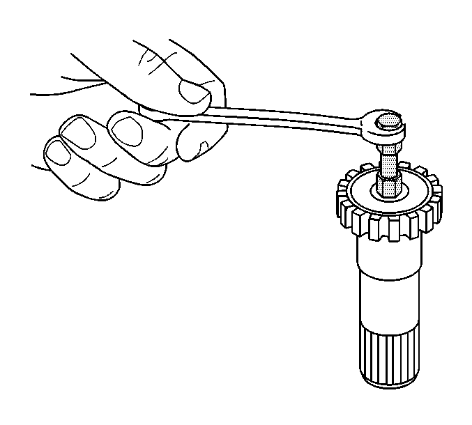
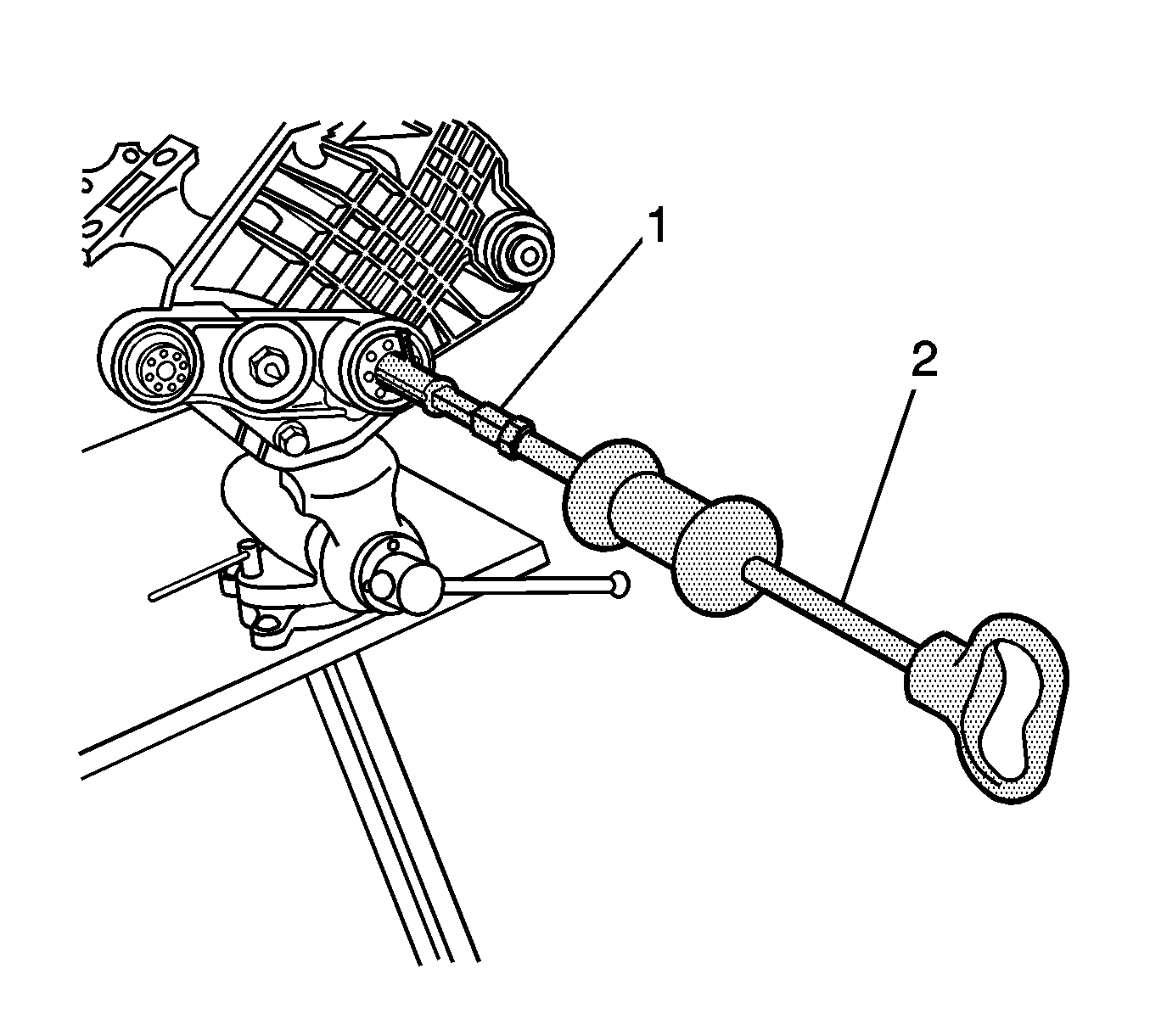
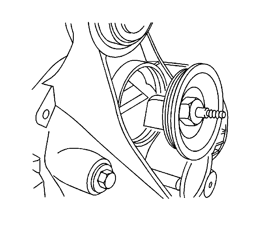
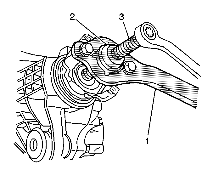
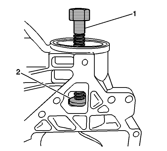
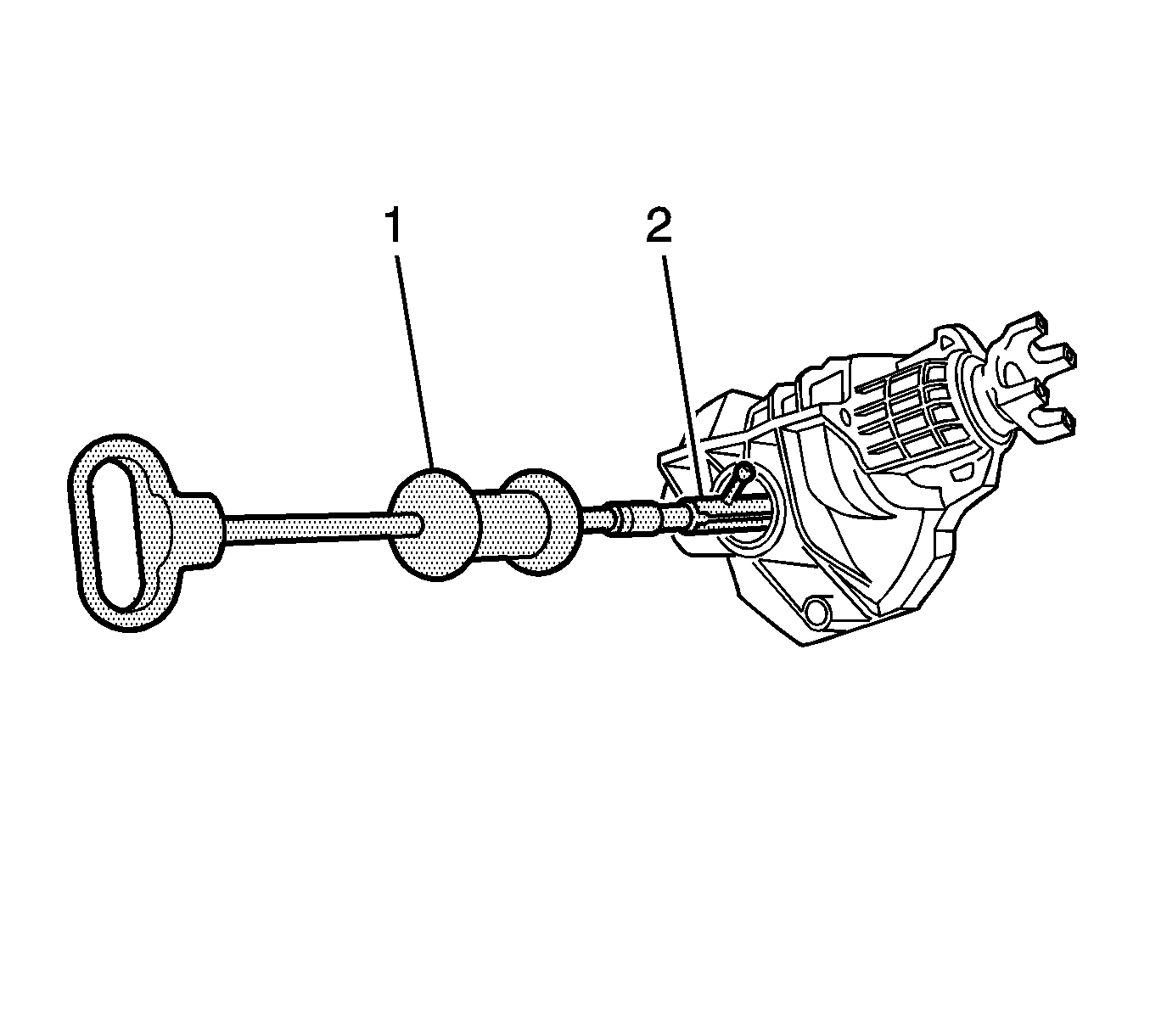
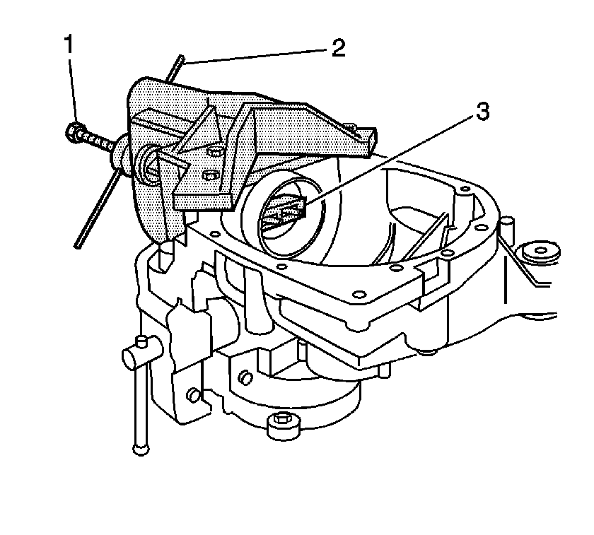
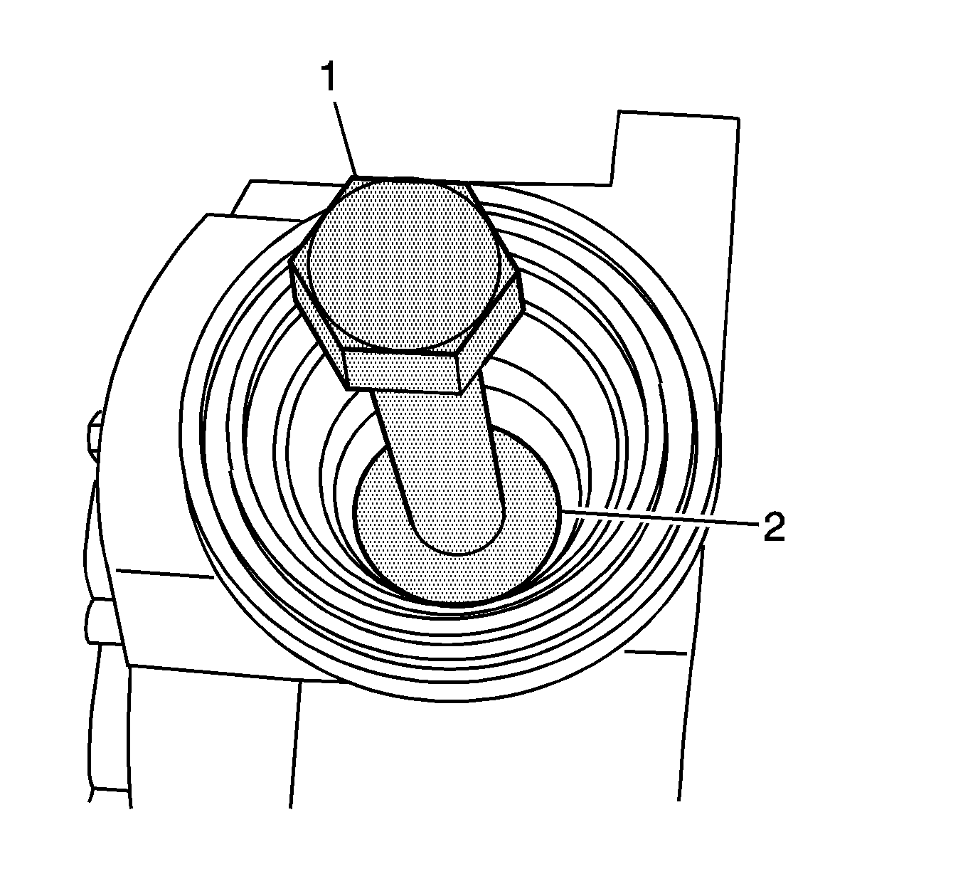
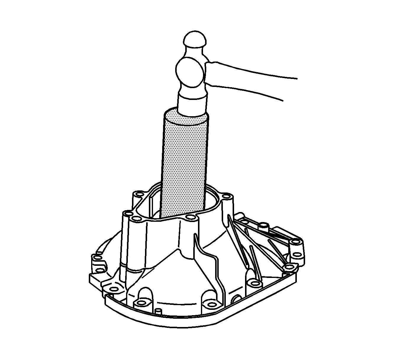
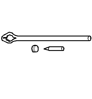
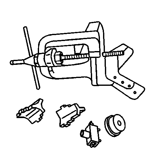
- Install the
J 8614-01
as shown.
Remove the pinion
nut while holding the
J 8614-01
.
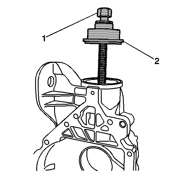
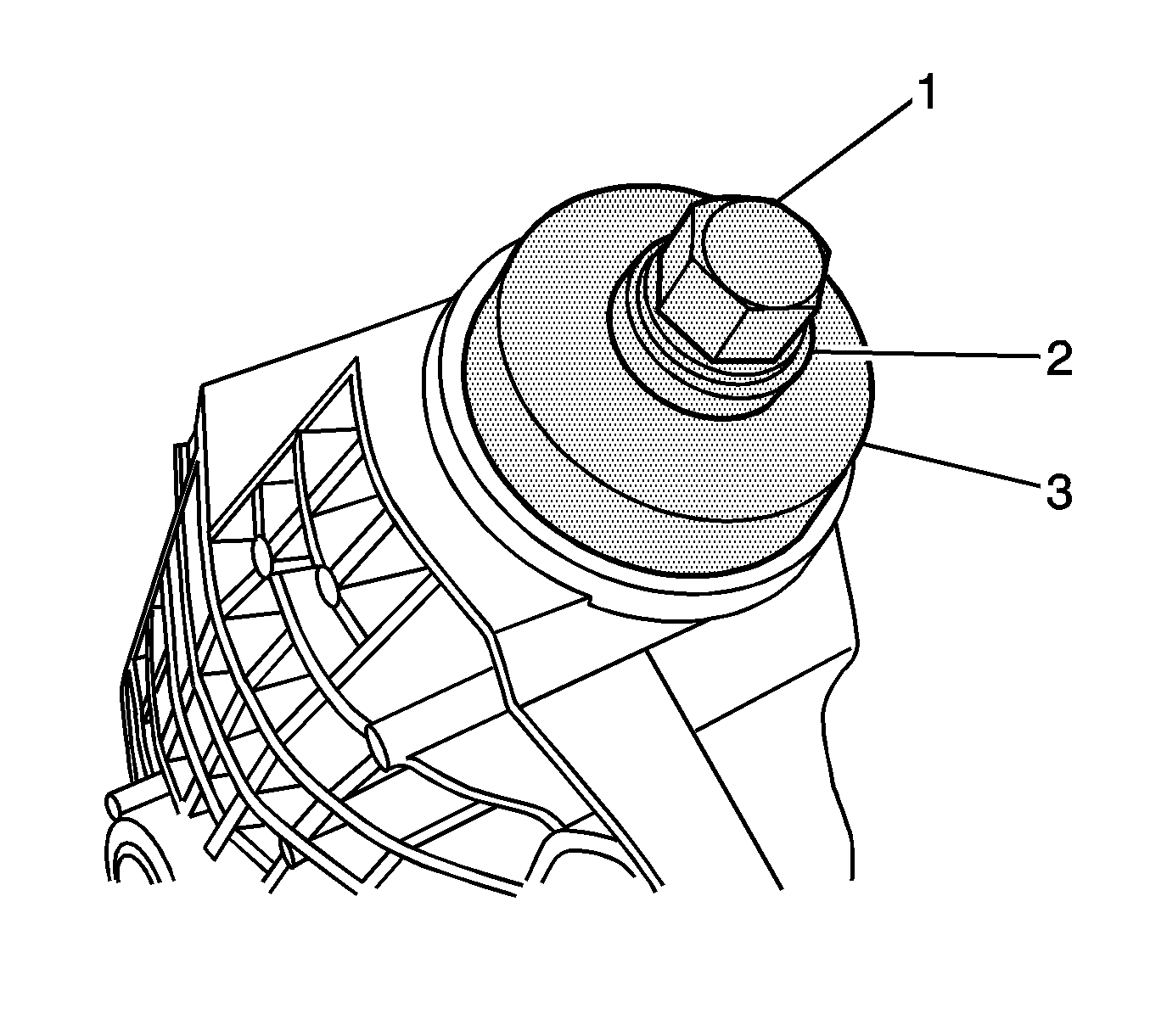
- Remove the washer.
- Install the J 8614-2 (2) and the J 8614-3 (3) into the
J 8614-01
(1) as shown.
- Remove the pinion yoke by turning the J 8614-3 (3) clockwise while holding the
J 8614-01
(1).
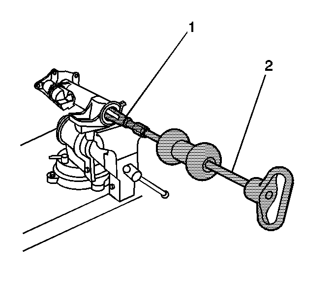
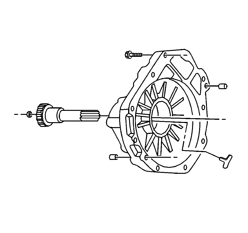
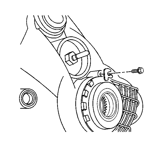
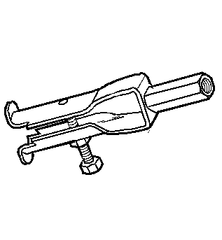
- Install the
J 45765
to the left side differential carrier
case half over the drive pinion as shown.
- Turn the forcing screw of the
J 45765
clockwise to remove the following components from the left side differential carrier case half:
| • | The pinion gear selectable shim |
| • | The inner pinion bearing |
- Remove the drive pinion seal using a suitable seal remover.
- Remove the outer pinion bearing from the differential carrier case half.
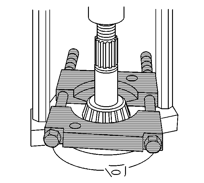
- Install the J 45754-3 over the inner pinion bearing
cup.
- Install the forcing screw (1) of the
J 45754
into the J 45754-3 (2).
- Drive out the inner pinion bearing cup by pounding on the forcing screw with a hammer.
- Install the J 45754-2 (2) and the forcing
screw (1) over the outer pinion bearing cup bore.
- Install the J 45754-4 (3) into the pinion bearing bore behind the
outer pinion bearing cup.
Slowly turn the forcing screw (1) until the J 45754-4 is evenly seated behind the outer pinion bearing cup bore and the J 45754-2 (2) is evenly seated over the outer pinion bearing cup bore.
- Remove the outer pinion bearing cup by turning the forcing screw clockwise.
- Install the
J 22912-B
between the pinion bearing and the drive pinion.
- Remove the inner pinion bearing using the
J 22912-B
and a hydraulic press.
- Remove the pinion gear selectable shim.
Differential Carrier Assembly Disassemble 8.25 Inch Axle Lock Tab Style
Tools Required
| • | J-45858
Front Axle Bearing Race Remover/Installer - 8.25 Inch Axle |
Inspection Procedure
Perform the following before disassembling the axle:
- Remove the drain plug from the axle.
- Drain the axle lubricant.
- Inspect the oil and the case for metal chips.
Determine the source of the metal chips, such as a broken gear or bearing cage.
- Check the ring gear backlash. Refer to
Backlash Inspection and Adjustment
.
This information can be used in order to determine the cause of the axle problem. The information will also help when setting up and preloading the differential case.
Determine the cause of the axle problem before disassembly, if possible.
Disassembly Procedure
- Install the differential carrier assembly in a vise.
- Remove the front axle actuator, S4WD axle only.
- Remove the inner axle shaft bearing and the inner axle shaft seal by performing
the following steps:
| 3.1. | Install the
J 29369-1
(1) behind the inner axle shaft bearing. |
| 3.3. | Using the
J 2619-01
, remove the inner axle shaft bearing and the seal . |
- Disconnect the right side inner axle shaft from the differential side gear using a hammer and a brass drift, F4WD axle only.
- Remove the inner axle shaft, F4WD axle only.
- Remove the inner axle shaft housing to differential carrier assembly bolts.
- Remove the inner axle shaft housing, F4WD axle only.
- Carefully remove the inner axle shaft
housing with the inner axle shaft and clutch fork components from the differential carrier assembly, S4WD axle only.
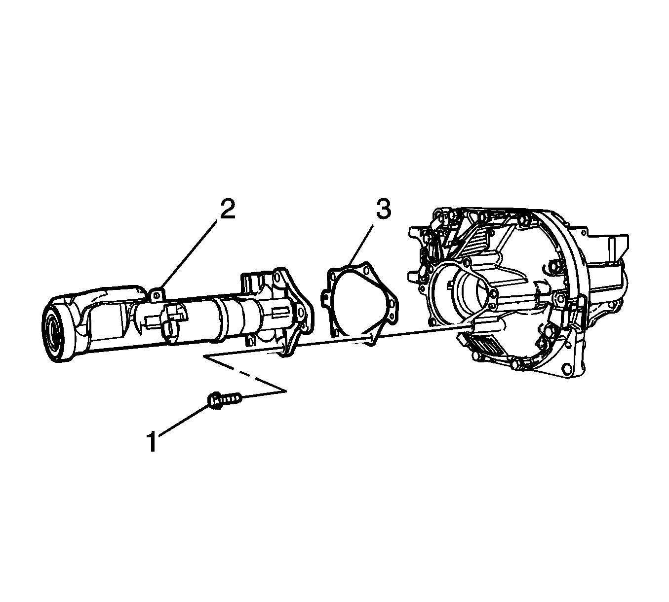
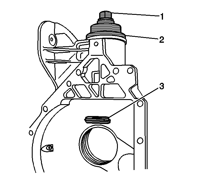
- Remove the inner axle housing bolt (1), axle shaft housing (2), and gasket (3).
- Remove the following components from the inner axle shaft
housing, S4WD axle only:
| 10.1. | The clutch fork inner spring (10) |
| 10.2. | The clutch fork assembly (11) |
| 10.3. | The clutch shaft shim (9) |
| 10.4. | The clutch shaft sleeve (8) |
| 10.5. | The front drive axle clutch gear (6) by doing the following: |
| 10.5.1. | Clamp the inner axle shaft housing (4) in a vise. |
Clamp only on the mounting flange.
| 10.5.2. | Strike the inside surface of the shaft (1) flange with a hammer and a brass drift in order to dislodge the front drive axle clutch gear (6) from the inner axle shaft (1). |
| 10.6. | Remove the front drive axle clutch gear (6) |
| 10.7. | Remove the thrust washer (5) |
| 10.8. | Remove the inner axle shaft (1) |
- Remove the inner axle shaft bearing and the inner axle shaft seal by performing the following steps:
| 11.1. | Place the differential carrier assembly into a vise. |
Clamp only on the mounting flange of the differential carrier assembly case.
| 11.2. | Install the
J 29369-1
(1) behind the inner axle shaft bearing. |
| 11.4. | Using the
J 2619-01
, remove the inner axle shaft bearing and the inner axle shaft seal . |
- Remove the differential carrier assembly from the vise.
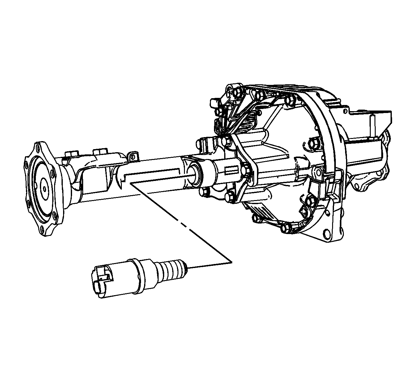
- Remove the front drive axle clutch shaft.
- Using the
J 34011
, remove
the clutch shaft bearing.
- Remove the vent connector.
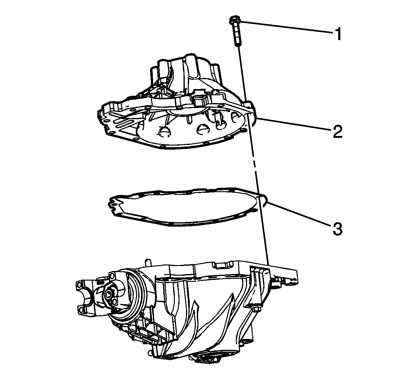
- Remove the differential carrier assembly bolts (1).
- Separate the left carrier case half from the right carrier case half (2) by tapping on the on the carrier case with a hammer and a brass drift.
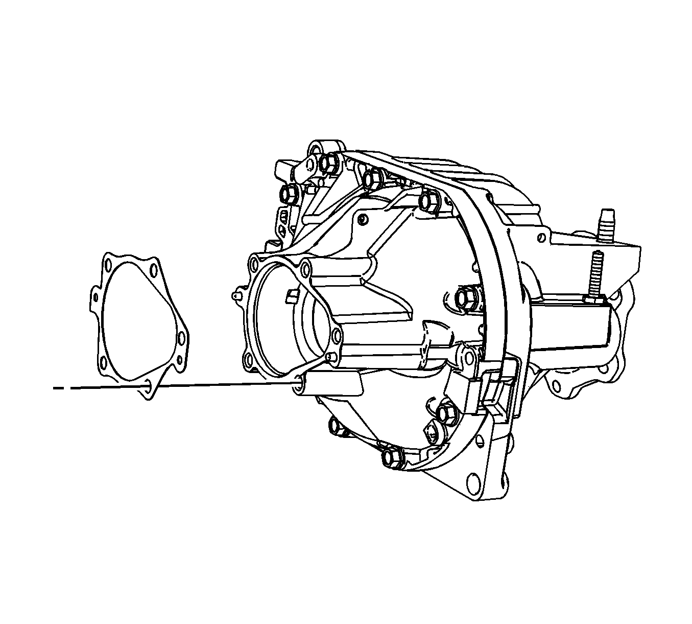
- Remove the differential carrier housing (2) and the differential carrier housing gasket (3).
- Remove the differential case assembly.
Disconnect the differential bearing adjuster nut locks from the differential bearing adjuster nut by prying up on the locks.
- Remove the differential bearing adjuster nuts and the differential bearing cups
by doing the following:
| 20.1. | Install the
J 36599-A
onto the differential bearing adjuster nut. |
| 20.2. | Turn the
J 36599-A
clockwise in order to push the differential bearing adjuster nut and the bearing cup out of the bore. |
- Remove the differential bearing adjuster nut sleeves using a hammer and brass drift.
- Install the
J 8614-01
as shown.
Remove the pinion nut while holding the
J 8614-01
.
- Remove the washer.
- Install the J 8614-2 (2) and the J 8614-3 (3) into the
J 8614-01
(1) as shown.
- Remove the pinion yoke by turning the J 8614-3 (3) clockwise while holding the
J 8614-01
(1).
- The steps below explain how to remove the drive pinion and pinion bearing cups using the
J 36598
or the
J 45765
and the
J-45858
. Follow the appropriate steps depending on what tool is available.
- Install the
J 36598
into a vise.
- Install the left differential carrier case half onto the
J 36598
and the J 36598-6.
- While holding the forcing screw of the
J 36598
, turn the handle of the
J 36598
counterclockwise in order to remove the pinion with the following
components:
| • | The pinion gear selectable shim |
| • | The inner pinion bearing |
- Install the J 36598-5 (3) behind the inner pinion bearing cup.
- Thread the forcing screw of the
J 36598
(1) onto the J 36598-5 (3) until fully seated.
- While holding the forcing screw of the
J 36598
(1), turn the handle of the
J 36598
(2) counterclockwise and press the inner bearing
cup out from the differential carrier case.
- Install the J 36598-5 (2) behind the outer
pinion bearing cup.
- Install the forcing screw of the
J 36598
(1) to the J 36598-5 (2).
- While holding the forcing screw of the
J 36598
, turn the handle of the
J 36598
clockwise in order to remove the following components:
| • | The pinion outer bearing |
| • | The pinion outer bearing cup |
- Install the
J 45765
to the left side differential carrier case half over the
drive pinion as shown.
- Turn the forcing screw of the
J 45765
clockwise to remove the following components from the left side differential carrier case half:
| • | The pinion gear selectable shim |
| • | The inner pinion bearing |
- Remove the drive pinion seal using a suitable seal remover.
- Remove the outer pinion bearing from the differential carrier case half.
- Install the J 45858-4 over the inner pinion bearing cup.
- Install the forcing screw (1) of the J 45858 into the J 45858-4 (2).
- Drive out the inner pinion bearing cup by pounding on the forcing screw with a hammer.
- Install the J 45858-3 (3), the thrust bearing and the washer (2),
and the forcing screw (1) over the outer pinion bearing cup bore.
- Install the J 45858-5 into the pinion bearing bore behind the outer pinion bearing cup.
Slowly turn the forcing screw clockwise until the J 45858-5 is evenly seated behind the outer pinion bearing cup bore and the J 45858-3 is evenly seated over the outer pinion bearing cup bore.
- Remove the outer pinion bearing cup by turning the forcing screw clockwise.
- Remove the collapsible spacer from the drive pinion.
- Install the
J 22912-B
between
the pinion bearing and the drive pinion.
- Using the
J 22912-B
and a hydraulic press, remove the inner pinion bearing
- Remove the pinion gear selectable shim.
Differential Carrier Assembly Disassemble 8.25 Inch Axle Lock Ring Style
Tools Required
| • | J 36614
Inner Pinion Bearing Installer |
| • | J-45858
Front Axle Bearing Race Remover/Installer - 8.25 Inch Axle |
Inspection Procedure
Perform the following before disassembling the axle:
- Remove the drain plug from the axle.
- Drain the axle lubricant.
- Inspect the oil and the case for metal chips.
Determine the source of the metal chips, such as a broken gear or bearing cage.
- Check the ring gear backlash. Refer to
Backlash Inspection and Adjustment.
This information can be used in order to determine the cause of the axle problem. The information will also help when setting up and preloading the differential case.
Determine the cause of the axle problem before disassembly, if possible.
Disassembly Procedure
- Install the differential carrier assembly in a vise.
- Remove the front axle actuator, S4WD axle only.
- Remove the left side inner axle shaft bearing and the inner axle shaft seal by performing the following steps:
| 3.1. | Install the
J 29369-1
(1) behind the inner axle shaft bearing. |
| 3.3. | Using the
J 2619-01
remove the inner axle shaft bearing and the seal. |
- Disconnect the right side inner axle shaft from the differential side gear using a hammer and a brass drift, F4WD axle only.
- Remove the inner axle shaft, F4WD axle only.
- Remove the inner axle shaft housing to differential carrier assembly bolts.
- Remove the inner axle shaft housing, F4WD axle only.
- Carefully remove the inner axle shaft
housing with the inner axle shaft and clutch fork components from the differential carrier assembly, S4WD axle only.
- Remove the inner axle housing to differential carrier gasket
- Remove the following components from the inner axle shaft
housing, S4WD axle only:
| 10.1. | The clutch fork inner spring (10) |
| 10.2. | The clutch fork assembly (11) |
| 10.3. | The clutch shaft shim (9) |
| 10.4. | The clutch shaft sleeve (8) |
| 10.5. | The front drive axle clutch gear (6) by doing the following: |
| 10.5.1. | Clamp the inner axle shaft housing (4) in a vise. |
Clamp only on the mounting flange.
| 10.5.2. | Strike the inside surface of the shaft (1) flange with a hammer and a brass drift in order to dislodge the front drive axle clutch gear (6) from the inner axle shaft (1). |
| 10.6. | Remove the front drive axle clutch gear (6) |
| 10.7. | Remove the thrust washer (5) |
| 10.8. | Remove the inner axle shaft (1) |
- Remove the right side inner axle shaft bearing and the inner axle shaft seal by
performing the following steps:
| 11.1. | Place the differential carrier assembly into a vise. |
Clamp only on the mounting flange of the differential carrier assembly case.
| 11.2. | Install the
J 29369-1
(1) behind the inner axle shaft bearing. |
| 11.4. | Using the
J 2619-01
(2), remove the inner axle shaft bearing and the inner axle shaft seal. |
- Remove the differential carrier assembly from the vise.
- Remove the front drive axle clutch shaft (S4WD only).
- Using the
J 34011
, remove
the clutch shaft bearing (S4WD only).
- Remove the vent connector.
- Remove the differential carrier assembly bolts (1).
- Separate the left carrier case half from the right carrier case half (2) by tapping on the on the carrier case with a hammer and a brass drift.
- Remove the differential carrier housing (2) and the differential carrier housing gasket (3).
- Remove the differential case assembly.
- Using a suitable remover, remove the differential bearing adjuster nut locks.
- Using the
J 36614
, remove the differential bearing adjuster nuts and the differential bearing cups.
- Install the
J 8614-01
as shown.
Remove the pinion nut while holding the
J 8614-01
.
- Remove the washer.
- Install the J 8614-2 (2) and the J 8614-3 (3) into the
J 8614-01
(1)
as shown.
- Remove the pinion yoke by turning the J 8614-3 (3) clockwise while holding the
J 8614-01
(1).
- The steps below explain how to remove the drive pinion and pinion bearing cups using the
J 36598
or the
J 45765
and the
J-45858
. Follow the appropriate steps depending on what tool is available.
- Install the
J 36598
into a vise.
- Install the left differential carrier case half onto the
J 36598
and the J 36598 - (only 3 of the 4 mounting bolts will be used).
- While holding the forcing screw of the
J 36598
, turn the handle of the
J 36598
counterclockwise in order to remove the pinion with the following
components:
| • | The pinion gear selectable shim |
| • | The inner pinion bearing |
- Install the J 36598-5 (3) behind the inner pinion bearing
cup.
- Thread the forcing screw of the
J 36598
(1) onto the J 36598-5 (3) until fully seated.
- While holding the forcing screw of the
J 36598
(1), turn the handle of the
J 36598
(2) counterclockwise and press the
inner bearing cup out from the differential carrier case.
- Install the J 36598-5 (2) behind the outer
pinion bearing cup.
- Install the forcing screw of the
J 36598
(1) to the J 36598-5 (2).
- While holding the forcing screw of the
J 36598
, turn the handle of the
J 36598
clockwise in order to remove the following components:
| • | The pinion outer bearing |
| • | The pinion outer bearing cup |
- Install the
J 45765
to the left side differential carrier case half over the
drive pinion as shown.
- Turn the forcing screw of the
J 45765
clockwise to remove the following components from the left side differential carrier case half:
| • | The pinion gear selectable shim |
| • | The inner pinion bearing |
- Remove the drive pinion seal using a suitable seal remover.
- Remove the outer pinion bearing from the differential carrier case half.
- Install the J 45858-4 over the inner pinion bearing cup.
- Install the forcing screw (1) of the
J-45858
into the J 45858-4 (2).
- Drive out the inner pinion bearing cup by pounding on the forcing screw with a hammer.
- Install the J 45858-3 (3), the thrust bearing and the washer (2), and the forcing screw (1) over the outer pinion bearing cup bore.
- Install the J 45858-5 into the pinion bearing bore behind the outer pinion bearing cup.
Slowly turn the forcing screw clockwise until the J 45858-5 is evenly seated behind the outer pinion bearing cup bore and the J 45858-3 is evenly seated over the outer pinion bearing cup bore.
- Remove the outer pinion bearing cup by turning the forcing screw clockwise.
- Remove the collapsible spacer from the drive pinion.
- Install the
J 22912-B
between
the pinion bearing and the drive pinion.
- Using the
J 22912-B
and a hydraulic press, remove the inner pinion bearing
- Remove the pinion gear selectable shim.
