Flushing NON-HP2
Special Tools
| • | J 42220
Universal 12V Leak Detection Lamp |
| • | J 43600
ACR 2000 Air Conditioning Service Center |
Important: Flushing with the ACR 2000 is not intended to remove metal from the A/C system.
Flushing is intended to remove the following contaminants:
| • | Contaminated polyalkylene glycol (PAG) oil |
| • | Desiccant, following a desiccant bag failure |
| • | Refrigerant contamination |
Important: Warmer engine or ambient temperature decreases the refrigerant recovery time during the A/C flush procedure.
- Recover the refrigerant. Refer to
Refrigerant Recovery and Recharging
.
- Remove the orifice tube. Refer to
Expansion (Orifice) Tube Replacement
.
- Connect the A/C lines with the orifice tube removed.
- Remove the A/C compressor. Refer to
Air Conditioning Compressor Replacement
.
- Inspect the end of the suction hose for a suction screen.
- Remove the suction screen, if installed.
- Install J 45268-4 to the A/C compressor suction hose.
- Install J 45268-5 to the A/C compressor discharge hose.

- Forward flow refrigerant flushing is recommended for contaminated refrigerant or PAG oil.
Perform the following procedure:
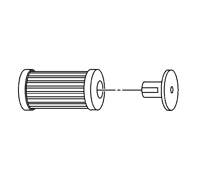
| | Important: The filter inside the J 45268-1 is serviceable. Remove and discard the check valve from the filter.
|
| 9.1. | Service the filter with ACDelco P/N GF 470, before each flush. |
Connect the J 45268-1 flush filter to the suction port of the J 45268-4 flush adapter.
| 9.2. | Connect the blue hose from the
J 43600
to the J 45268-1 flush filter adapter. |
| 9.3. | Connect the red hose from the
J 43600
to the J 45268-5 flush adapter. |
- Reverse flow refrigerant flushing is recommended for desiccant bag failure. Perform the following procedure and replace the accumulator when the flush procedure is complete.
| | Important: The filter inside the J 45268-1 is serviceable. Remove and discard the check valve from the filter.
|
| 10.1. | Service the filter with AC P/N GF 470, before each flush. Connect the J 45268-1 flush filter to the discharge port of the J 45268-5 flush adapter. |
| 10.2. | Connect the blue hose from the
J 43600
to the J 45268-1 flush filter adapter. |
| 10.3. | Connect the red hose from the
J 43600
to the suction port of the J 45268-4 flush adapter. |
Important: Close the valve on the external refrigerant tank, before starting the flush process.
- Flush the front A/C system. Follow the instructions supplied with the
J 43600
.
Important: Flush the front A/C system before flushing the auxiliary A/C system.
- If the vehicle is equipped with rear A/C, flush the auxiliary A/C system separately.

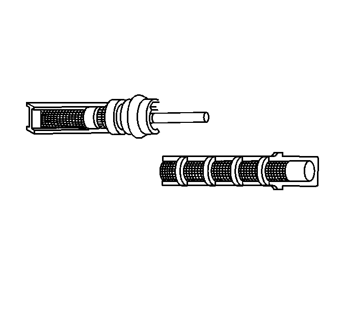
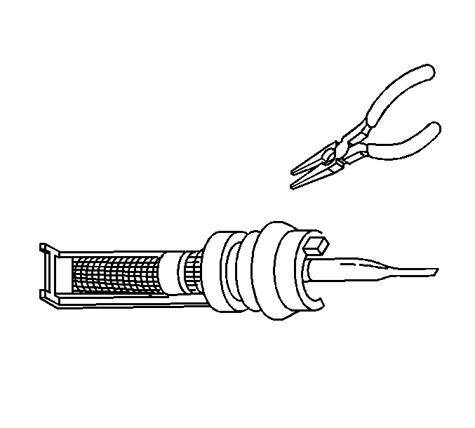
- Cut the orifice tube frame and screen, enough to access the end of the orifice tube. Pinch off the orifice tube.

Important: Pinch off the orifice tube in order to prevent refrigerant flow to the front system during the auxiliary system flush.
- Install the pinched orifice tube. Refer to
Expansion (Orifice) Tube Replacement
.
- Remove the auxiliary thermal expansion valve (TXV). Refer to
Auxiliary Air Conditioning Evaporator Thermal Expansion Valve Replacement
.
- Install the J 45268-121.
Important: The auxiliary evaporator core can be flushed without totally reassembling into the auxiliary HVAC module.
- Install the auxiliary evaporator core to the A/C lines.
- Raise the vehicle. Refer to
Lifting and Jacking the Vehicle
.
- Connect the auxiliary A/C lines to the auxiliary evaporator core.
- Lower the vehicle.
- Flush the auxiliary A/C system. Follow the instructions supplied with the
J 43600
.
- Raise the vehicle. Refer to
Lifting and Jacking the Vehicle
.
- Remove the auxiliary A/C lines from the auxiliary evaporator core.
- Lower the vehicle.
- Remove the J 45268-121.
- Inspect the TXV for debris.
Clean or replace as needed.
- Install the auxiliary TXV. Refer to
Auxiliary Air Conditioning Evaporator Thermal Expansion Valve Replacement
.
- Remove the J 45268-4 from the A/C compressor suction hose.
- Remove the J 45268-5 from the A/C compressor discharge hose.
Important: Flushing will remove all the PAG oil from the A/C system.
The A/C system must be replenished with the correct amount of PAG oil.
- If the removed A/C compressor is being reinstalled, perform the following procedure:
| • | Drain the PAG oil from the A/C compressor. |
| • | Rotate the compressor input shaft to assist in draining the PAG oil from the A/C compressor. |
- If you will replace the A/C compressor after flushing the system, perform the following procedure:
| 31.2. | If the service compressor is shipped with PAG oil, DO NOT drain the new PAG oil from the compressor. |
| 31.3. | Deduct the amount of PAG oil shipped with the service compressor from the amount of PAG oil listed in the capacities table. Refer to
Refrigerant System Capacities
. |
| 31.4. | Add the calculated amount to the compressor, as needed. |
Important: Flushing will remove the fluorescent leak detection dye from the A/C system.
- Add one bottle of
J 41447
directly to the A/C compressor.
- Install the A/C compressor. Refer to
Air Conditioning Compressor Replacement
.
- Install a new orifice tube. Refer to
Expansion (Orifice) Tube Replacement
.
- Evacuate and recharge the A/C system. Refer to
Refrigerant Recovery and Recharging
.
- Leak test the fittings using
J 42220
.
Flushing HP2
Special Tools
| • | J 42220
Universal 12V Leak Detection Lamp |
| • | J 43600
ACR 2000 Air Conditioning Service Center |
ACR2000 (J-43600) Hose Flush Procedure
Important:
| • | The following hose flushing procedure must be performed every time the ACR2000 (J-43600) is used on the hybrid vehicles. It must be completed before the ACR2000 (J-43600) is connected to the vehicle to begin a diagnostic or service procedure. |
| • | The high voltage (HV) electric air conditioning (A/C) compressor on these two-mode hybrid vehicles uses a polyolester (POE) refrigerant oil instead of a polyalkylene glycol (PAG) synthetic refrigerant oil. This is due to the better electrical resistance
of the POE oil and its ability to provide HV isolation. |
| • | The following hose flush procedure is required to prevent oil cross-contamination. Laboratory testing has shown that flushing the ACR2000 (J-43600) using the following procedure will minimize oil cross-contamination to a negligible amount (<500ppm). |
| • | Failure to flush the ACR2000 (J-43600) hoses before adding refrigerant to a hybrid vehicle with an electric A/C compressor may result in an unacceptable amount of PAG oil entering the refrigerant system. It may also cause a battery energy control
module hybrid battery voltage system isolation lost diagnostic trouble code (DTC P1AE7) to be set. Additionally the A/C system warranty will be voided. |
| • | The ACR2000 (J-43600) will need to be retrofitted with a J-43600-50 (Hose-ACR2000 Oil Flush Loop) to be able to perform the following procedure. All hybrid dealers will receive a J-43600-50, with installation instructions, which is
a component of the hybrid essential tool package. Dealers not included in the hybrid marketing plan and needing to service a hybrid vehicle can obtain the J-43600-50 from SPX Kent Moore, 1-800-GM-TOOLS (1-800-468-6657). |
| - | The J-43600-50 Retrofit Kit replaces the existing hose mount fittings on the ACR2000. Installation instructions are included to properly update the ACR2000 for hybrid vehicle A/C service. |
| - | New hybrid compliant A/C refrigerant recharging equipment (GE-48800) will be released in January 2008 for dealers to replace current ACR2000 equipment. GE-48800 meets new SAE refrigerant recovery standard J-2788 and is specially designed for GM hybrid
vehicle A/C service. |
Before Beginning the Hose Flushing Procedure
- Always allow the ACR2000 to complete the hose flush cycle to assure that all oil and refrigerant is removed from the hoses and the ACR2000 flow control circuit.
- Assure the ACR2000 has at least 4.08 kg (9 lb) of chargeable refrigerant before proceeding.
- A Low Filter Flow message displayed during the hose flushing process indicates that the hose couplers are not connected or open.
Hose Flushing Procedure
- Connect the ACR2000 service hose couplers to the J-43600-50 hose flush adapter fittings and open the service hose coupler valves.
- Power on the ACR2000.
- If there is positive pressure in the ACR2000 service hoses, press START to recover the service hoses. If there is 88-98 kPa (26-29 Hg) of vacuum showing on the display screen, skip to step 7.
- Press Vacuum.
- Press Start. Allow the vacuum program to run until the display screen shows between 88-98 kPa (26-29 Hg).
- Press Pause.
- Press Main Menu.
- Press Scroll Menu.
- Press Oil Flush.
- Press Next.
- Enter 03:00 (for a three minute flush) and press Start.
- The ACR2000 will now flush the service hoses for three minutes and then recover the refrigerant
- Close the ACR2000 service hose couplers and remove the J-43600-50 hose flush adapter.
- The ACR2000 can now be connected to the hybrid vehicle to perform the A/C system diagnostic or service procedures.
Important: Flushing with the ACR 2000 is not intended to remove metal from the A/C system.
Flushing is intended to remove the following contaminants:
| • | Contaminated polyolester (POE) oil |
| • | Desiccant, following a desiccant bag failure |
| • | Refrigerant contamination |
Important: Warmer engine or ambient temperature decreases the refrigerant recovery time during the A/C flush procedure.
- Recover the refrigerant. Refer to
Refrigerant Recovery and Recharging.
- Remove the orifice tube. Refer to
Expansion (Orifice) Tube Replacement.
- Connect the A/C lines with the orifice tube removed.
- Remove the A/C compressor. Refer to
Air Conditioning Compressor Replacement.
- Inspect the end of the suction hose for a suction screen.
- Remove the suction screen, if installed.
- Install J 45268-4 to the A/C compressor suction hose.
- Install J 45268-5 to the A/C compressor discharge hose.

- Forward flow refrigerant flushing is recommended for contaminated refrigerant or POE oil.
Perform the following procedure:
| | Important: The filter inside the J 45268-1 is serviceable. Remove and discard the check valve from the filter.
|
| 9.1. | Service the filter with ACDelco P/N GF 470, before each flush. |
Connect the J 45268-1 flush filter to the suction port of the J 45268-4 flush adapter.
| 9.2. | Connect the blue hose from the
J 43600
to the J 45268-1 flush filter adapter. |
| 9.3. | Connect the red hose from the
J 43600
to the J 45268-5 flush adapter. |
- Reverse flow refrigerant flushing is recommended for desiccant bag failure. Perform the following procedure and replace the accumulator when the flush procedure is complete.
| | Important: The filter inside the J 45268-1 is serviceable. Remove and discard the check valve from the filter.
|
| 10.1. | Service the filter with AC P/N GF 470, before each flush. Connect the J 45268-1 flush filter to the discharge port of the J 45268-5 flush adapter. |
| 10.2. | Connect the blue hose from the
J 43600
to the J 45268-1 flush filter adapter. |
| 10.3. | Connect the red hose from the
J 43600
to the suction port of the J 45268-4 flush adapter. |
Important: Close the valve on the external refrigerant tank, before starting the flush process.
- Flush the front A/C system. Follow the instructions supplied with the
J 43600
.
Important: Flush the front A/C system before flushing the auxiliary A/C system.
- If the vehicle is equipped with rear A/C, flush the auxiliary A/C system separately.

- Cut the orifice tube frame and screen, enough to access the end of the orifice tube. Pinch off the orifice tube.

Important: Pinch off the orifice tube in order to prevent refrigerant flow to the front system during the auxiliary system flush.
- Install the pinched orifice tube. Refer to
Expansion (Orifice) Tube Replacement.
- Remove the auxiliary thermal expansion valve (TXV). Refer to
Auxiliary Air Conditioning Evaporator Thermal Expansion Valve Replacement.
- Install the J 45268-121.
Important: The auxiliary evaporator core can be flushed without totally reassembling into the auxiliary HVAC module.
- Install the auxiliary evaporator core to the A/C lines.
- Raise the vehicle. Refer to
Lifting and Jacking the Vehicle.
- Connect the auxiliary A/C lines to the auxiliary evaporator core.
- Lower the vehicle.
- Flush the auxiliary A/C system. Follow the instructions supplied with the
J 43600
.
- Raise the vehicle. Refer to
Lifting and Jacking the Vehicle.
- Remove the auxiliary A/C lines from the auxiliary evaporator core.
- Lower the vehicle.
- Remove the J 45268-121.
- Inspect the TXV for debris.
Clean or replace as needed.
- Install the auxiliary TXV. Refer to
Auxiliary Air Conditioning Evaporator Thermal Expansion Valve Replacement.
- Remove the J 45268-4 from the A/C compressor suction hose.
- Remove the J 45268-5 from the A/C compressor discharge hose.
Important: Flushing will remove all the POE oil from the A/C system.
The A/C system must be replenished with the correct amount of POE oil.
- If the removed A/C compressor is being reinstalled, perform the following procedure:
| • | Drain the POE oil from the A/C compressor. |
- If you will replace the A/C compressor after flushing the system, perform the following procedure:
| 31.2. | DO NOT drain the new POE oil from the compressor. |
| 31.3. | Deduct the amount of POE oil shipped with the service compressor from the amount of POE oil listed in the capacities table. Refer to
Refrigerant System Capacities. |
| 31.4. | Add the calculated amount to the compressor, as needed. |
Important: Flushing will remove the fluorescent leak detection dye from the A/C system.
- Replace the A/C accumulator assembly. Refer to
Air Conditioning Accumulator Replacement.
Note: The serviced accumulator assembly is manufactured with POE fluorescent leak detection dye wafer inside.
- Install the A/C compressor. Refer to
Air Conditioning Compressor Replacement.
- Install a new orifice tube. Refer to
Expansion (Orifice) Tube Replacement.
- Evacuate and recharge the A/C system. Refer to
Refrigerant Recovery and Recharging.
- Leak test the fittings using
J 42220
.


