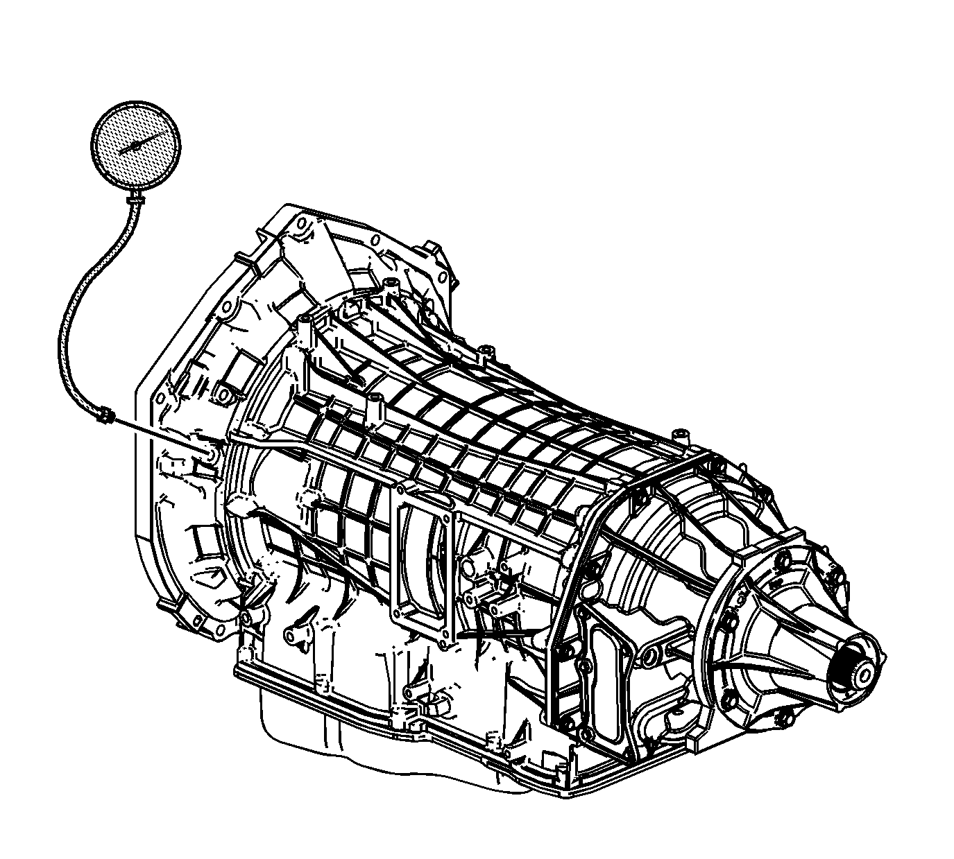
Main Fluid Pump

Special Tools
J 21867 Pressure Gage
- Install a scan tool.
- Start the engine.
- Inspect the transmission for the proper fluid level. Refer to Transmission Fluid Check.
- Use the scan tool to inspect for any active or stored diagnostic trouble codes. If there are any DTC's, refer to that DTC table first.
- Inspect the manual linkage at the transmission for proper function.
- Turn the engine OFF.
- Remove the line pressure test hole plug.
- Install the J 21867 .
- Access the Scan Tool Transmission Output Controls for the Line PC Solenoid.
- Start the engine.
- Use the scan tool to increase and decrease the Line PC Solenoid in increments of approximately 100 KPa (15 psi). The scan tool commands the increment values automatically.
- Allow the pressure to stabilize between increments.
- Compare your pressure readings on the scan tool to those indicated on the J 21867 .
- If the pressure readings vary greatly, refer to Main Fluid Pump Pressure High or Low.
- Turn the engine OFF.
- Remove the J 21867 .
- Install the line pressure test hole plug.
Caution: Keep the brakes applied at all times in order to prevent unexpected vehicle motion. Personal injury may result if the vehicle moves unexpectedly.
Caution: When the transmission is at operating temperatures, take necessary precautions when removing the auxiliary pump pressure test hole plug, to avoid being burned by the catalytic converter.
Important: You may need to remove or disconnect components in order to gain access to the transmission line pressure test hole plug.
Important: In order to achieve accurate line pressure readings, the following procedure must be performed at least 3 times in order to gather uniform pressure readings. Also if you do not have the hood open the engine may go in to AutoStop.
The scan tool is only able to control the line PC solenoid in PARK and NEUTRAL with engine speeds below 1500 RPM. This protects the clutches from extreme high or low line pressures.Notice: Use the correct fastener in the correct location. Replacement fasteners must be the correct part number for that application. Fasteners requiring replacement or fasteners requiring the use of thread locking compound or sealant are identified in the service procedure. Do not use paints, lubricants, or corrosion inhibitors on fasteners or fastener joint surfaces unless specified. These coatings affect fastener torque and joint clamping force and may damage the fastener. Use the correct tightening sequence and specifications when installing fasteners in order to avoid damage to parts and systems.
Tighten
Tighten the pressure plug to 11 N·m (97 lb in).
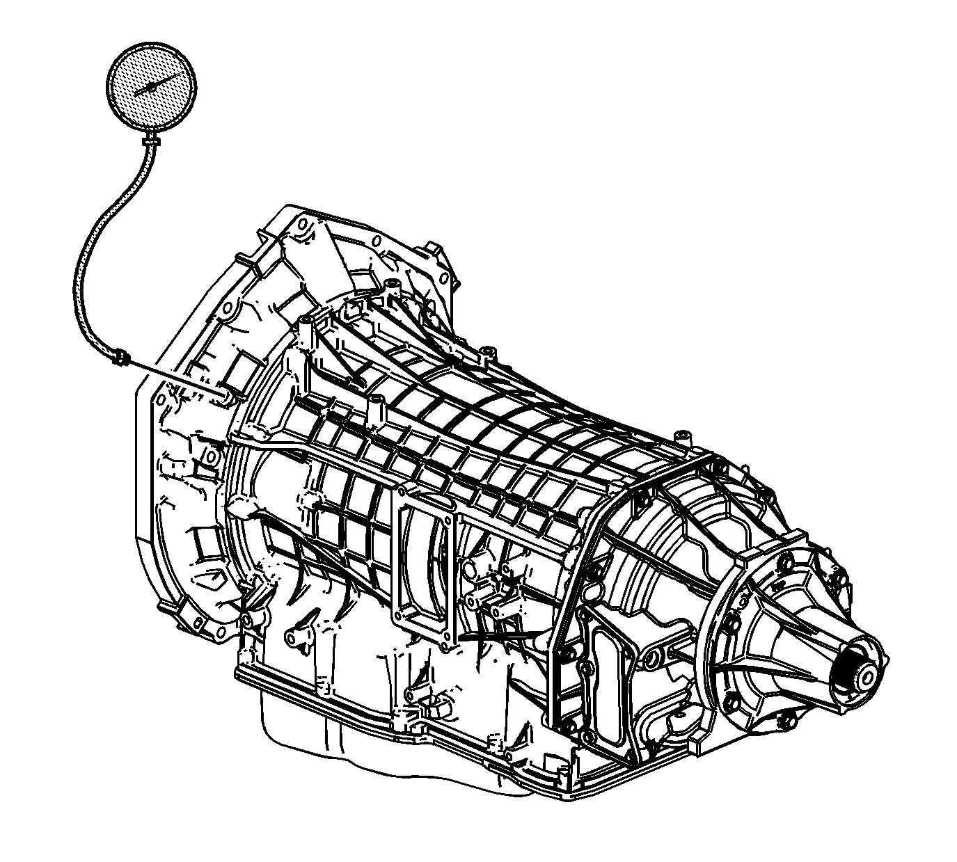
Auxiliary Fluid Pump

Special Tools
J 21867 Pressure Gage
- Install a scan tool.
- Start the engine.
- Inspect the transmission for the proper fluid level. Refer to Transmission Fluid Check.
- Use the scan tool to inspect for any active or stored diagnostic trouble codes. If there are any DTC's refer to that DTC table.
- Inspect the manual linkage at the transmission for proper function.
- Turn the engine OFF.
- Remove the auxiliary pump pressure test hole plug.
- Install the J 21867 .
- Access the Scan Tool Hybrid Output Controls for the Aux Trans Pump Speed.
- Turn key to the Run Position but do not start the engine.
- Use the scan tool to increase and decrease the Aux Pump Speed in increments of approximately 10%. The scan tool commands the increment values automatically starting with 10% going up to 80% and returning down to 30%.
- Allow the pressure to stabilize between increments.
- Your pressure readings on the J 21867 should slightly increase with each speed command. The J 21867 at 10% should be approximately 40-70 PSI and end up at 80% being approximately 90-120 PSI.
- If the pressure readings vary greatly, refer to Auxiliary Fluid Pump Pressure High or Low.
- Turn the key OFF.
- Remove the J 21867 .
- Install the auxiliary pump pressure test hole plug.
Caution: Keep the brakes applied at all times in order to prevent unexpected vehicle motion. Personal injury may result if the vehicle moves unexpectedly.
Caution: When the transmission is at operating temperatures, take necessary precautions when removing the auxiliary pump pressure test hole plug, to avoid being burned by the catalytic converter.
Important: You may need to remove or disconnect components in order to gain access to the transmission auxiliary pump pressure test hole plug.
Important: In order to achieve accurate aux pump pressure readings, the following procedure must be performed at least 3 times in order to gather uniform pressure readings.
Notice: Use the correct fastener in the correct location. Replacement fasteners must be the correct part number for that application. Fasteners requiring replacement or fasteners requiring the use of thread locking compound or sealant are identified in the service procedure. Do not use paints, lubricants, or corrosion inhibitors on fasteners or fastener joint surfaces unless specified. These coatings affect fastener torque and joint clamping force and may damage the fastener. Use the correct tightening sequence and specifications when installing fasteners in order to avoid damage to parts and systems.
Tighten
Tighten the pressure plug to 11 N·m (97 lb in).
