Torsion Bar and Support Assembly Replacement Bushing Style
Tools Required
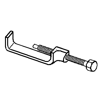
J 36202 Torsion Bar Unloading/Loading Tool
Removal Procedure
Important: When lifting the vehicle to service the torsion bars or related components, DO NOT lift the vehicle by the front suspension. Use the appropriate hoist and lift the vehicle by the frame.
- Raise and support the vehicle. Refer to Lifting and Jacking the Vehicle.
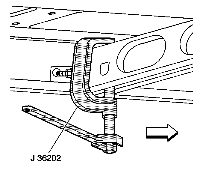
- Install the J 36202 to the adjustment arm and the crossmember.
- Using the J 36202 , increase the tension on the adjustment arm until the load is removed from the adjustment bolt and the adjuster nut.
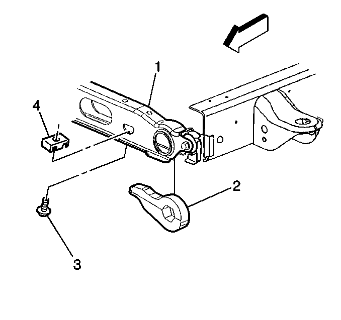
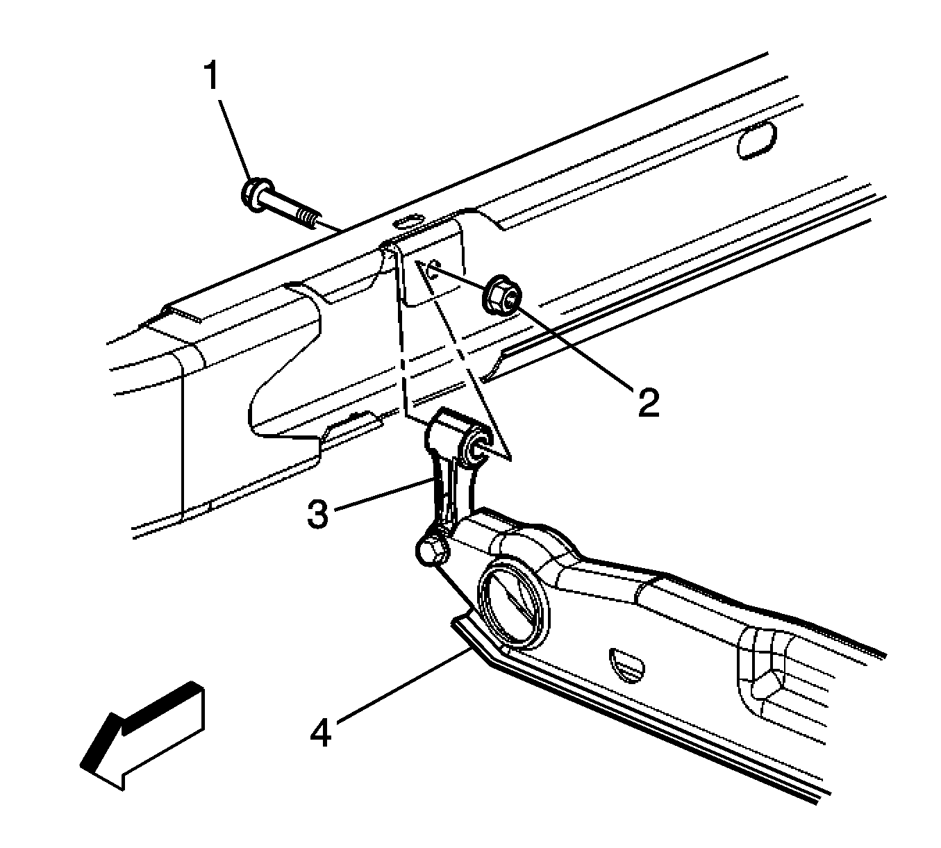
- Remove the adjustment bolt (3) and the adjust nut (4) from the crossmember (1).
- Remove the J 36202 , allowing the torsion bar to unload.
- Remove the adjustment arm (2) by sliding the torsion bar forward.
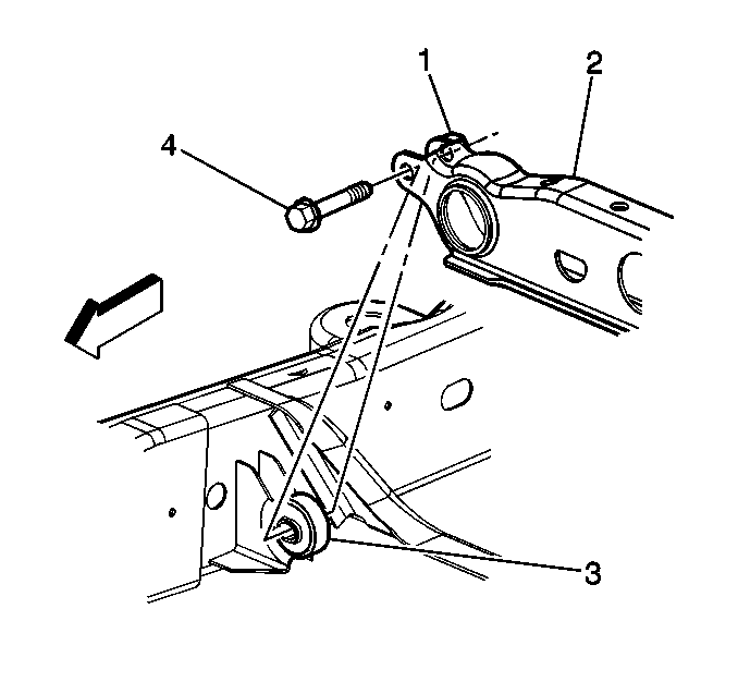
- Remove the torsion bar crossmember bolt (4) from the weld nut (1).
- Remove the crossmember (2) from the crossmember mount (3).
- Remove the torsion bar from the crossmember.
- Remove the torsion bars from the vehicle.
Notice: Use care when handling the torsion bars in order to avoid chipping or scratching the coating. Damage to the coating will result in premature failure of the torsion bars.
Important: Mark the adjustment bolt and count the number of times that is required to remove the adjustment bolt.
Important: The left and right torsion bars are different and are not interchangeable.
Installation Procedure
- Position the torsion bar in the lower control arm.
- Install the torsion bar in the crossmember (2) on the crossmember mount (3).
- Install the torsion bar crossmember bolt (4) in the weld nut (1).
- Install the adjustment arm (2) in the crossmember (1).
- Install the adjuster bolt (3) and the adjuster nut (4).
- Install the torsion bar into the adjustment arm until the torsion bar is fully seated.
- Install the J 36202 to the adjustment arm and the crossmember.
- Using the J 36202 , increase the tension on the adjustment arm to load the torsion bar.
- Turn the adjuster bolt the same amount of turns as it took to remove it.
- Remove the J 36202 from the crossmember.
- Remove the safety stands and lower the vehicle.
- Measure the Z height. Refer to Trim Height Inspection.
Notice: Refer to Fastener Notice in the Preface section.
Tighten
Tighten the crossmember bolt to 95 N·m (70 lb ft).
Torsion Bar and Support Assembly Replacement Link Style
Tools Required
J 36202 Torsion Bar Unloading/Loading Tool
Removal Procedure
Important: When lifting the vehicle to service the torsion bars or related components, DO NOT lift the vehicle by the front suspension. Use the appropriate hoist and lift the vehicle by the frame.
- Raise and support the vehicle. Refer to Lifting and Jacking the Vehicle.
- Install the J 36202 to the adjustment arm and the support assembly.
- Using the J 36202 , increase the tension on the adjustment arm until the load is removed from the adjustment bolt and the adjuster nut.
- Remove the adjustment bolt (3) and the adjuster nut (4) from the support assembly (1).
- Remove the J 36202 , allowing the torsion bar to unload.
- Remove the adjustment arm (2) by sliding the torsion bar forward.
- Remove the adjustment arm (2) from the support assembly (1).
- Remove the upper link mounting bolt (1) and nut (2) from the link (3).
- Remove the torsion bar support assembly (4).
- Remove the torsion bar from the vehicle.
Notice: Use care when handling the torsion bars in order to avoid chipping or scratching the coating. Damage to the coating will result in premature failure of the torsion bars.

Important: Create a reference point for the adjustment bolt to the support. Count the number of times that is required to remove the adjustment bolt.
Important: The left and right torsion bars are different and are not interchangeable
Installation Procedure
- Position the torsion bar in the lower control arm.
- Install the torsion bar in the support assembly.
- Install the upper link mounting nut (2) and the bolt (1) in the link (3).
- Install the adjustment arm (2) in the support assembly (1).
- Install the adjuster bolt (3) and the adjustment nut (4).
- Slide the torsion bar rearward until the torsion bar is fully seated in the adjustment arm.
- Install the J 36202 on the adjustment arm and the support assembly.
- Using the J 36202 , increase the tension on the adjustment arm in order to load the torsion bar.
- Align the reference marks, turn the adjuster bolt the same amount of turns as it took to remove it.
- Remove the J 36202 from the support assembly.
- Remove the safety stand and lower the vehicle.
- Measure the Z height. Refer to Trim Height Inspection.
Notice: Refer to Fastener Notice in the Preface section.
Tighten
Tighten the nut to 95 N·m (70 lb ft).
