Front Wheel Hub, Bearing, and Seal Replacement 1500
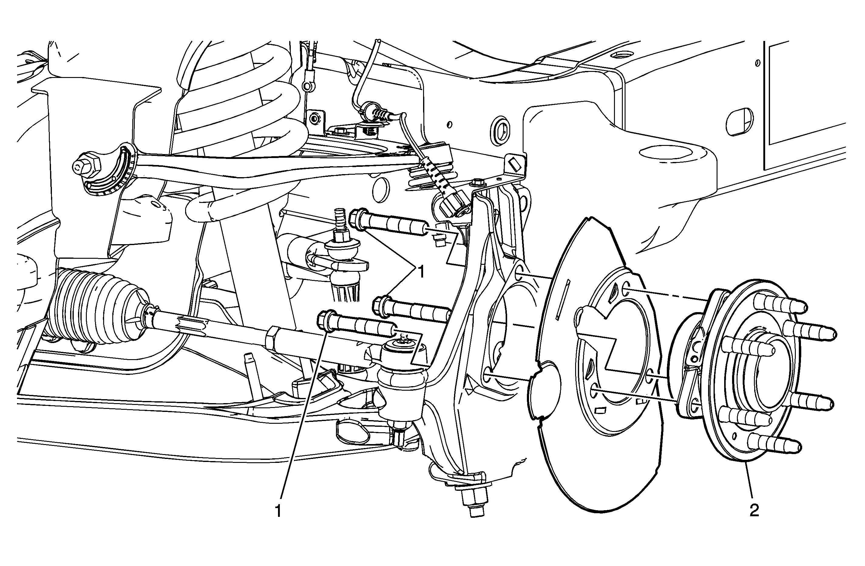
Callout | Component Name |
|---|---|
Preliminary Procedure
| |
1 | Wheel Bearing and Hub Bolt (Qty: 3) Notice: Refer to Fastener Notice in the Preface section. Tighten |
2 | Wheel Hub and Bearing Assembly |
Front Wheel Hub, Bearing, and Seal Replacement 2500
Removal Procedure
- Raise and support the vehicle. Refer to Lifting and Jacking the Vehicle .
- Remove the tire and wheel. Refer to Tire and Wheel Removal and Installation .
- Remove the rotor. Refer to Front Brake Rotor Replacement .
- Remove the wheel speed sensor and brake hose mounting bracket bolt from the steering knuckle.
- Disconnect the electrical connection for the wheel speed sensor.
- Remove the wheel driveshaft nut retaining cover.
- Wrap shop towel around the inner and outer wheel drive shaft booth. .
- Remove the wheel driveshaft assembly retaining nut and washer from the wheel driveshaft assembly. Refer to Wheel Drive Shaft Replacement
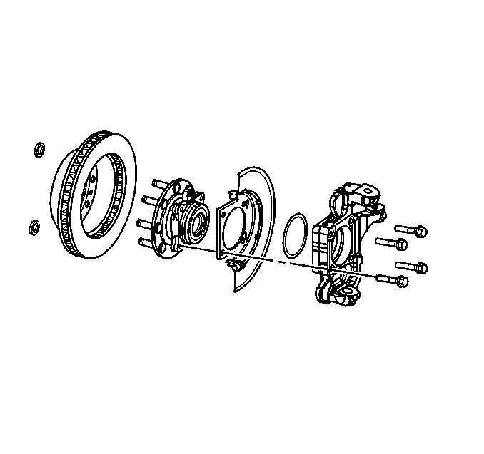
- Remove the wheel hub and bearing mounting bolts.
- Remove the wheel hub and bearing and splash shield from the vehicle.
- Remove the O-ring seal from the steering knuckle bore.
- Remove the wheel speed sensor from the wheel hub and bearing.
- Clean and inspect the O-ring seal.
- Replace the seal if the following conditions exist:
Notice: Never place vehicle on the ground with the halfshaft removed or the halfshaft nut torqued improperly. Otherwise, bearing seals may become dislodged causing premature wear and/or damage to the hub and bearing assembly.
Important: Steps 6 thru 8 applies to those vehicles equipped with 4WD
Notice: Wheel drive shaft boots, seals and clamps should be protected from sharp objects any time service is performed on or near the wheel drive shaft(s). Damage to the boot(s), the seal(s) or the clamp(s) may cause lubricant to leak from the joint and lead to increased noise and possible failure of the wheel drive shaft.
| • | Nicks |
| • | Cuts |
| • | Dry or brittle |
| • | Compression set |
Installation Procedure
- Clean all corrosion or contaminates from the steering knuckle bore and the hub and bearing assembly.
- Lubricate the steering knuckle bore with wheel bearing grease or the equivalent.
- Install the O-ring to the steering knuckle.
- Install the wheel speed sensor to the wheel hub and bearing.
- Install the wheel hub and bearing and splash shield to the vehicle.
- Install the wheel hub and bearing mounting bolts.
- Install the nut and washer retaining the wheel drive shaft assembly to the wheel hub and bearing. Refer to Wheel Drive Shaft Replacement
- Connect the electrical connection for the wheel speed sensor.
- Install the wheel speed sensor and brake hose mounting bracket bolt to the steering knuckle.
- Install the rotor. Refer to Front Brake Rotor Replacement .
- Install the tire and wheel. Refer to Tire and Wheel Removal and Installation .
- Lower the vehicle .
Notice: Refer to Fastener Notice in the Preface section.
Tighten
Tighten the sensor mounting bolt to 18 N·m (13 lb ft).
Tighten
Tighten the wheel hub to knuckle bolts to 180 N·m (133 lb ft).
Important: The following service procedure applies to those vehicles equipped with 4WD.
Tighten
Tighten the bolt to 12 N·m (106 lb in).
