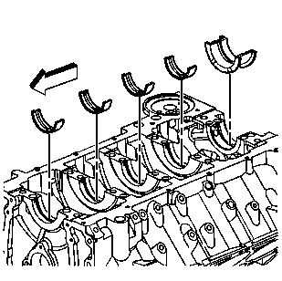
Important:
| • | Lubricate the crankshaft bearings and crankshaft with clean engine oil. |
| • | If undersized bearings are used, ensure that the bearings are fitted to the proper journals. |
- Install the crankshaft upper bearings into the block. Apply clean engine oil to the bearing surfaces.
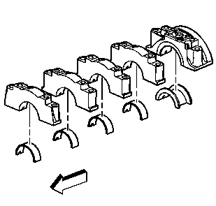
- Install the crankshaft lower bearings into the crankshaft bearing caps. Apply clean engine oil to the bearing
surfaces.
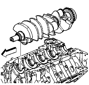
Notice: In order to prevent damage to the crankshaft position (CKP)
sensor reluctor wheel/ring, care must be used when removing or installing this component.
- Install the crankshaft.
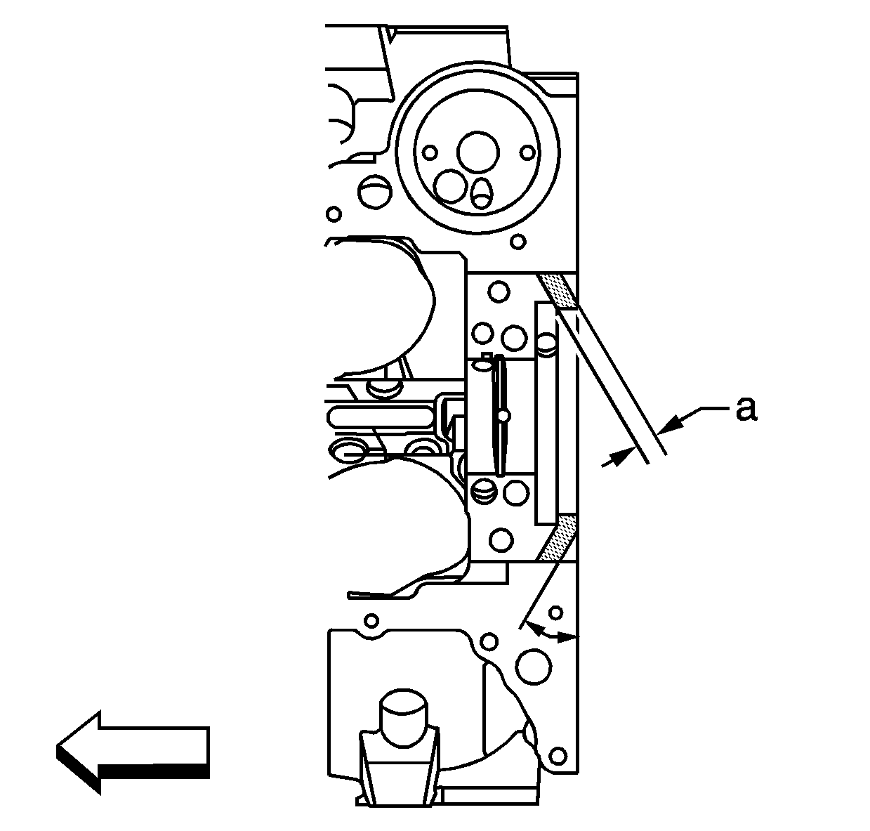
Important: The bearing caps must be seated within 60 minutes of the sealer being applied. The bearing cap fasteners must be tightened within 5 minutes of the bearing caps being installed onto the engine block.
- Apply a 13 mm (0.5 in) (a) light film of sealant GM P/N 1052942, (Canadian P/N 10953466), or equivalent, to the rear bearing cap sealing face or to the rear bearing cap channel of the engine block. Apply
the sealant to the bearing cap mating surface and bearing cap channel from the rear seal bore to the oil pan surface.
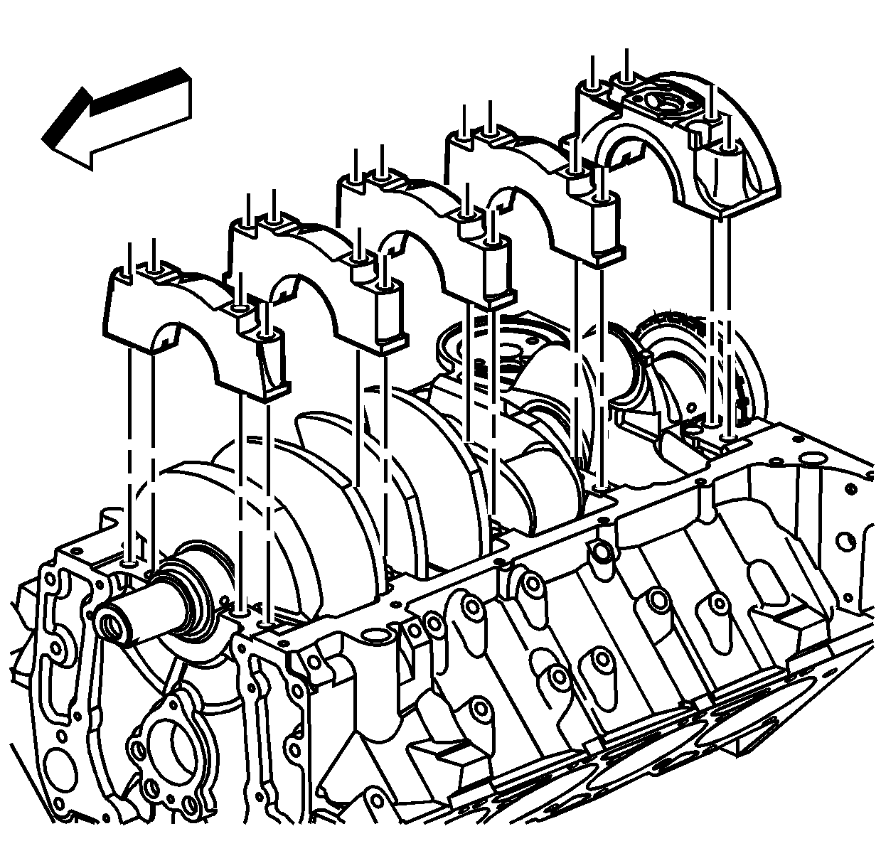
Notice: In order to prevent the possibility of cylinder block or
crankshaft bearing cap damage, the crankshaft bearing caps are tapped into
the cylinder block cavity using a brass, lead, or a leather mallet before
the attaching bolts are installed. Do not use attaching bolts to pull the
crankshaft bearing caps into the seats. Failure to use this process may damage
a cylinder block or a bearing cap.
Notice: The crankshaft position
(CKP) sensor reluctor wheel/ring is not serviced separately. Do not repair the CKP sensor reluctor wheel/ring. If the CKP sensor reluctor ring is damaged, the crankshaft assembly must be replaced.
Important: Ensure the triangle symbols on the crankshaft bearing caps are facing the front of the engine.
- Install the crankshaft bearing caps in the location the caps were marked and originally removed from.
Notice: Refer to Fastener Notice in the Preface section.
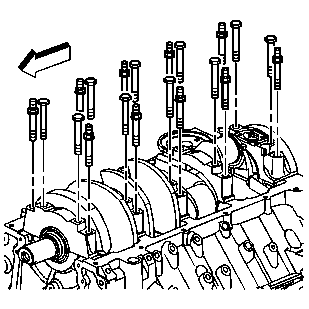
Important: Tighten the crankshaft bearing cap bolts before tightening the crankshaft bearing cap studs.
- Install the bearing cap bolts and studs.
Tighten
- Tighten the bearing cap 1-4 bolts a first pass to 30 N·m (22 lb ft).
- Tighten the bearing cap 1-4 studs a first pass to 30 N·m (22 lb ft).
- Tighten the bearing cap 1-4 bolts a final pass an additional 90 degrees, using the
J 45059
.
- Tighten the bearing cap 1-4 studs a final pass an additional 80 degrees, using the
J 45059
.
- Tighten the bearing cap 5 bolts and studs to 30 N·m (22 lb ft).
- Loosen the bearing cap 5 bolts and studs.
- Tighten the bearing cap 5 bolts and studs to 5 N·m (44 lb in).
- Thrust the crankshaft firmly rearward.
- Thrust the crankshaft firmly forward.
Tighten
- Tighten the bearing cap 5 bolts a first pass to 30 N·m (22 lb ft).
- Tighten the bearing cap 5 studs a first pass to 30 N·m (22 lb ft).
- Tighten the bearing cap 5 bolts a final pass an additional 90 degrees, using the
J 45059
.
- Tighten the bearing cap 5 bolts a final pass an additional 80 degrees, using the
J 45059
.
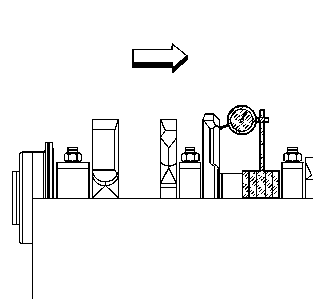
- Measure the crankshaft end play as follows:
| 9.1. | Install the
J 8001
, or equivalent, to the cylinder block, with the dial indicator plunger against one of the counterweights of the crankshaft. |
| 9.2. | Firmly thrust the end of the crankshaft first rearward then forward. This lines up the rear crankshaft bearing and the crankshaft thrust surfaces. |
| 9.3. | With the crankshaft pushed forward, zero the dial indicator. Move the crankshaft rearward, and read the end play measurement on the dial indicator. An optional method is to insert a feeler gage between the crankshaft and the bearing surface and measure
the clearance. Refer to
Engine Mechanical Specifications
. |
| 9.4. | If the correct end play cannot be obtained, inspect for the following conditions: |
| 9.5. | Turn the crankshaft in order to inspect for binding. If the crankshaft does not turn freely, loosen the crankshaft bearing bolts and studs, 1 cap at a time, until the tight bearing is located. The following conditions could cause a lack of
clearance at the bearing: |
| • | Burrs on the crankshaft bearing cap |
| • | Foreign material between the bearing and the block |
| • | Foreign material between the bearing and the bearing cap |
| • | A faulty crankshaft bearing |
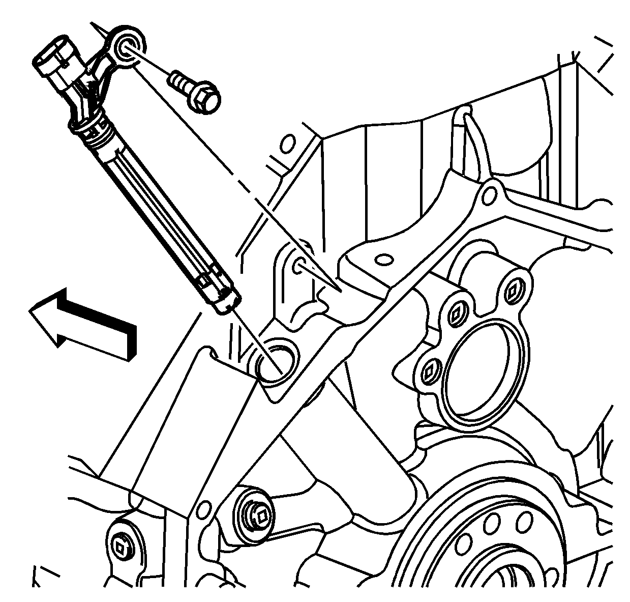
Important:
| • | Ensure that the CKP sensor is fully seated against the crankshaft reluctor ring. The upper flange on the sensor MAY NOT seat against the engine block. |
| • | The CKP sensor bolt has thread sealant applied to the threads. The thread sealant may have come off during bolt removal. Ensure the bolt hole is clean of any debris before installing the CKP sensor bolt. |
- Inspect the CKP sensor O-ring for cuts, cracks, tears, or damage. Replace the O-ring, as needed. Lubricate the CKP sensor O-ring with clean engine oil.
- Install the CKP sensor into the block. There may be a slight resistance as the O-ring seats into the engine block.
- Apply thread adhesive GM P/N 12345493 (Canadian P/N 10953488), or equivalent, to the CKP sensor bolt.
- Install the CKP sensor bolt.
Tighten
Tighten the CKP sensor bolt to 12 N·m (106 lb in).


