Caution: Do not attempt to cage the compression (power) spring when the rear air brake chamber shows structural damage. Caging the compression spring or disassembly of the spring brake chamber may result in the forceful release of the compression (power) spring and the chamber contents which may cause severe personal injury. Remove the entire rear air brake chamber if it has structural damage and replace with a new rear air brake chamber.
Caution: Do not drive the vehicle with the rear air brake chambers caged. Caging the rear air brake chambers disables the emergency and parking brakes. If a malfunction occurs with the service brakes, serious personal injury could result from not having any emergency brakes.
- Block the wheels.
- Start the engine.
- Charge the system to the air compressor governor valve cut-out point.
- Stop the engine.
- Inspect the rear air brake chamber for any structural damage.
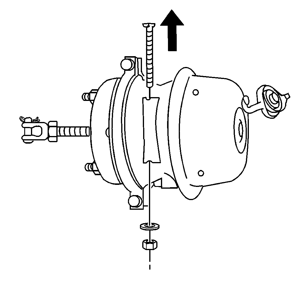
- Remove the dust plug from the release tool keyhole in the center of the rear air brake chamber.
- Remove the release tool assembly from the side pocket of the adapter.
- Cage the rear air brake chambers in the following order:
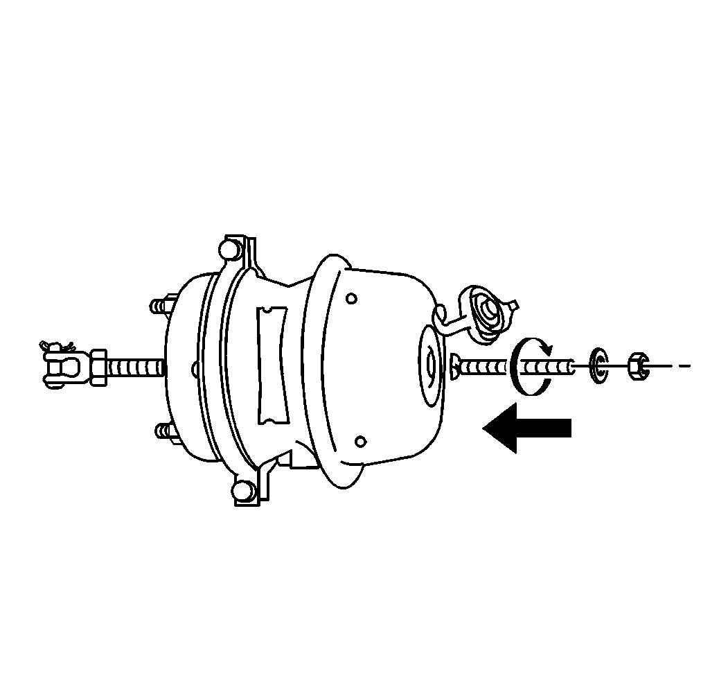
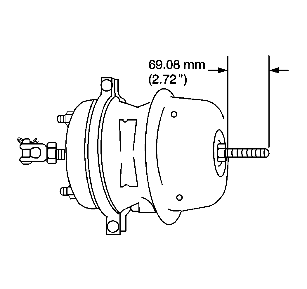
- Measure the release stud length beyond the release stud nut.
- Replace the rear air brake chamber if the stud length is less than 69.08 mm (2.72 in). Refer to Rear Air Brake Chamber Replacement .
- Tighten the release stud.
- Ensure that the pushrod is retracting.
- Ensure that the compression spring is completely caged.
- Measure the release stud length beyond the release stud nut.
- Replace the rear air brake chamber if the stud length is less than 69.08 mm (2.72 in). Refer to Rear Air Brake Chamber Replacement .
Important: Do not apply the parking brake.
Do not cage the compression spring if there is any damage to the rear air brake chamber. Refer to Rear Air Brake Chamber Overhaul .
Caution: If air pressure is used to compress the compression spring, do not tighten the release nut more than finger tight. Torquing the release nut too tight may cause pressure plate damage resulting in the sudden release of the compression spring causing severe personal injury.
| 8.1. | Insert the release stud through the keyhole in the rear air brake chamber, the spring brake chamber section, into the pressure plate. |
| 8.2. | Turn the release stud 90 degrees (1/4 turn) clockwise. |
| 8.3. | Pull on the release stud in order to ensure the release stud crosspin is properly seated in the pressure plate. |
| Notice: Tighten the release stud nut no more than finger tight if air pressure is used to compress the compression (power) spring. |
| 8.4. | Assemble the release stud washer and the nut on the release stud finger tight. |
Caution: Do not torque the release stud more than the torque specified when caging the compression spring. If the specified release stud length cannot be obtained at the maximum allowed torque, there may be a broken compression spring. Do not attempt to disassemble any part of the spring brake chamber if the spring is broken. Replace the rear air brake chamber. Failure to observe this caution may result in sever personal injury.
Notice: Do not use an impact wrench to tighten the release nut. Damage to the pressure plate and release stud can occur.
Important: Tighten the release stud nut only if the rear air brake chamber, spring brake chamber section, is not pressurized.
Tighten
Tighten the release stud nut to a maximum of 47 N·m (35 lb ft).
