Power Brake Booster Inlet Hose Replacement L18, LLY and LMM
Removal Procedure
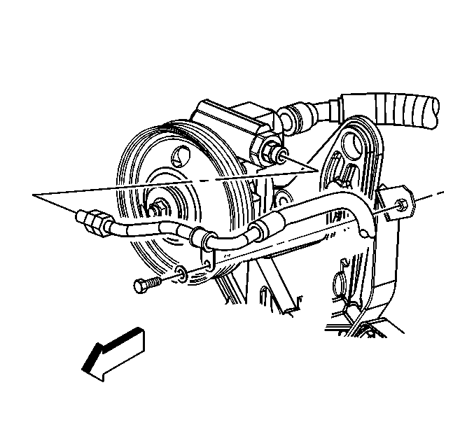
- Remove the tie-wraps and the hose insulators.
- Disconnect the hydraulic brake booster inlet hose from the of the power steering pump. Refer to Power Steering Hose Quick Connect Fitting .
- Disconnect the hydraulic brake booster inlet hose from the hydraulic brake booster.
- Remove the hydraulic brake booster inlet hose from vehicle.
Important: Note the position of all the tie-wraps, power steering hoses and the hose insulators for proper re-installation.
Installation Procedure
Notice: Do not start the engine with any power steering hose disconnected, or damage to the components could occur.
- Install the hydraulic brake booster inlet hose to vehicle.
- Install the hydraulic brake booster inlet hose to the hydraulic brake booster.
- Connect the hydraulic brake booster inlet hose to the power steering pump. Refer to Power Steering Hose Quick Connect Fitting .
- Install the tie wraps and the hose insulators.
- Bleed the system. Refer to Power Steering System Bleeding .
Notice: Refer to Fastener Notice in the Preface section.
Tighten
Tighten the hydraulic brake booster inlet hose fittings to 27 N·m (20 lb ft).
Power Brake Booster Inlet Hose Replacement LB7
Removal Procedure
- Remove the tie-wraps and the hose insulators.
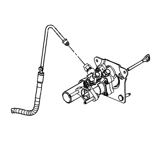
- Disconnect the hydraulic brake booster inlet hose from the of the power steering gear outlet. Refer to Power Steering Hose Quick Connect Fitting .
- Remove the clips and isolators holding the power brake booster inlet hose to the frame and body.
- Disconnect the hydraulic brake booster inlet hose from the hydraulic brake booster.
- Remove the hydraulic brake booster inlet hose from vehicle.
Important: Note the position of all the tie-wraps, power steering hoses and the hose insulators for proper re-installation.
Installation Procedure
Notice: Do not start the engine with any power steering hose disconnected, or damage to the components could occur.
- Install the hydraulic brake booster inlet hose to vehicle.
- Install the hydraulic brake booster inlet hose to the hydraulic brake booster.
- Install the clips and isolators holding the power brake booster inlet hose to the frame and body.
- Connect the hydraulic brake booster inlet hose to the power steering gear. Refer to Power Steering Hose Quick Connect Fitting .
- Install the tie wraps and the hose insulators.
- Bleed the system. Refer to Power Steering System Bleeding .
Notice: Refer to Fastener Notice in the Preface section.
Tighten
Tighten the hydraulic brake booster inlet hose fittings to 27 N·m (20 lb ft).
Power Brake Booster Inlet Hose Replacement LG4/LG5/LF6 and LF8
Removal Procedure
- Remove the tie-wraps and the hose insulators.
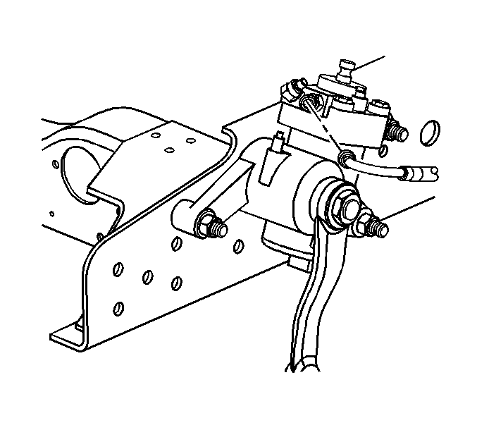
- Disconnect the hydraulic brake booster inlet hose from the hydraulic brake booster.
- Disconnect the hydraulic brake booster inlet hose from the of the power steering pump. Refer to Power Steering Hose Quick Connect Fitting .
- Remove the hydraulic brake booster inlet hose from vehicle.
Important: Note the position of all the tie-wraps, power steering hoses and the hose insulators for proper re-installation.

Installation Procedure
Notice: Do not start the engine with any power steering hose disconnected, or damage to the components could occur.
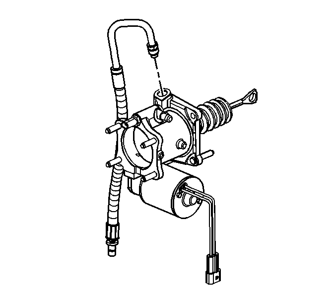
- Connect the hydraulic brake booster inlet hose to the of the power steering pump. Refer to Power Steering Hose Quick Connect Fitting .
- Install the hydraulic brake booster inlet hose to vehicle.
- Connect the hydraulic brake booster inlet hose to the hydraulic brake booster.
- Install the tie wraps and the hose insulators.
- Bleed the system. Refer to Power Steering System Bleeding .
Notice: Use the correct fastener in the correct location. Replacement fasteners must be the correct part number for that application. Fasteners requiring replacement or fasteners requiring the use of thread locking compound or sealant are identified in the service procedure. Do not use paints, lubricants, or corrosion inhibitors on fasteners or fastener joint surfaces unless specified. These coatings affect fastener torque and joint clamping force and may damage the fastener. Use the correct tightening sequence and specifications when installing fasteners in order to avoid damage to parts and systems.
Tighten
Tighten the hydraulic brake booster inlet hose fittings to 27 N·m (20 lb ft).
