Removal Procedure
- Set the parking brake.
- Block the front wheels.
- Raise the vehicle frame using a suitable lifting device in order to remove the weight of the vehicle from the spring assembly.
Support the frame forward of the rear axle.
- Remove the rear dual wheel assembly, if necessary. Refer to
Tire and Wheel Removal and Installation
.
- Remove the following components:
- Remove the shock absorber. Refer to
Shock Absorber Replacement
.
- Remove the U-bolt nuts and washers.
- Remove the following components:
| • | The U-bolt anchor plate |
| • | The shock absorber bracket |
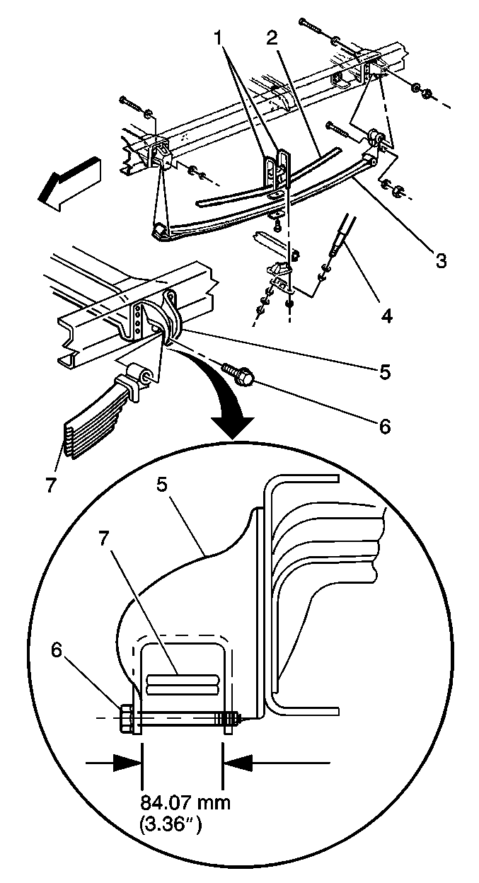
- Remove the U-bolts (1).
- Remove the seat.
- Lower the axle slightly.
- Remove the following components:
- Support and raise the vehicle using a suitable lifting device in order to provide clearance between the spring assembly and the hanger bracket.
Support the frame forward of the rear axle.
- Remove the following components:
| • | The auxiliary spring bolt |
- Remove the spring assembly (7) using a suitable hoist.
Installation Procedure
- Install the spring assembly onto the axle pad or axle stabilizer/spring seat, if equipped, using a suitable hoist.
Important: Always install NEW U-bolts when loosened or removed.
- Install the following components:
- Install the U-bolt spacer over the center bolt.
- Install the U-bolts into the spacer grooves.
- Install the U-bolt anchor plate (1) and seat.
- Install the shock absorber bracket or stabilizer shaft/spring seat, if equipped.
Notice: Refer to Fastener Notice in the Preface section.
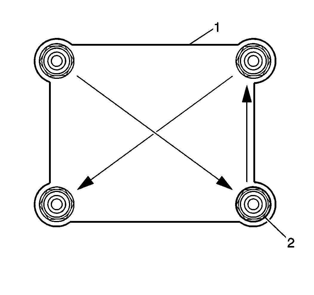
Important: In order to properly tighten the U-bolt nuts, torque the nuts progressively as outlined below.
- On 4500 and 5500 series axles, install the 20 mm (0.787 in) U-bolts, nuts (2), and washers:
Tighten
- Tighten the U-bolt nuts to 100 N·m (74 lb ft) in sequence.
- Tighten the U-bolt nuts to 250 N·m (184 lb ft) in sequence.
- Tighten the U-bolt nuts to 300 N·m (220 lb ft) in sequence.
- On 6500, 7500, and 8500 series axles, install proper U-bolt, nuts (2), and washers:
Tighten
- Tighten the U-bolt nuts to 150 N·m (111 lb ft) in sequence.
- Tighten the U-bolt nuts to 275 N·m (203 lb ft) in sequence.
- On 6500, 7500, and 8500 series, 20 mm (0.787) U-bolt nuts, tighten the nuts to 330 N·m (243 lb ft) in sequence.
- On 6500, 7500, and 8500 series, 22 mm (0.866 in) U-bolt nuts, tighten the nuts to 415 N·m (308 lb ft) in sequence.
- Install the following components:
| • | The spring eye bolt nut |
Tighten
Tighten the spring front eye bolt to 415 N·m (305 lb ft).
- Install the shock absorber. Refer to
Shock Absorber Replacement
.
Tighten
Tighten the lower shock absorber nut to 61 N·m (45 lb ft).
- Lower the frame until the hangers touch the surface of the spring eye.
- For tapered leaf springs, install the following components:
| • | The rear spring hanger rebound bolt |
Tighten
Tighten the bolt to 415 N·m (305 lb ft).
- For multileaf springs, install the rear spring eye bolt.
Tighten
| • | On 6500, 7500, and 8500 series, tighten the spring eye bolt to 485 N·m (358 lb ft). |
| • | On 4500 and 5500 series, tighten the spring eye bolt to 415 N·m (305 lb ft). |
