Fuel Sender Assembly Replacement 15 Gallon
Tools Required
J 45722 Fuel Sender Lock Ring Wrench
Removal Procedure
- Remove the fuel tank. Refer to Fuel Tank Replacement .
- Disconnect the fuel lines from the sending unit. Refer to Metal Collar Quick Connect Fitting Service or Plastic Collar Quick Connect Fitting Service .
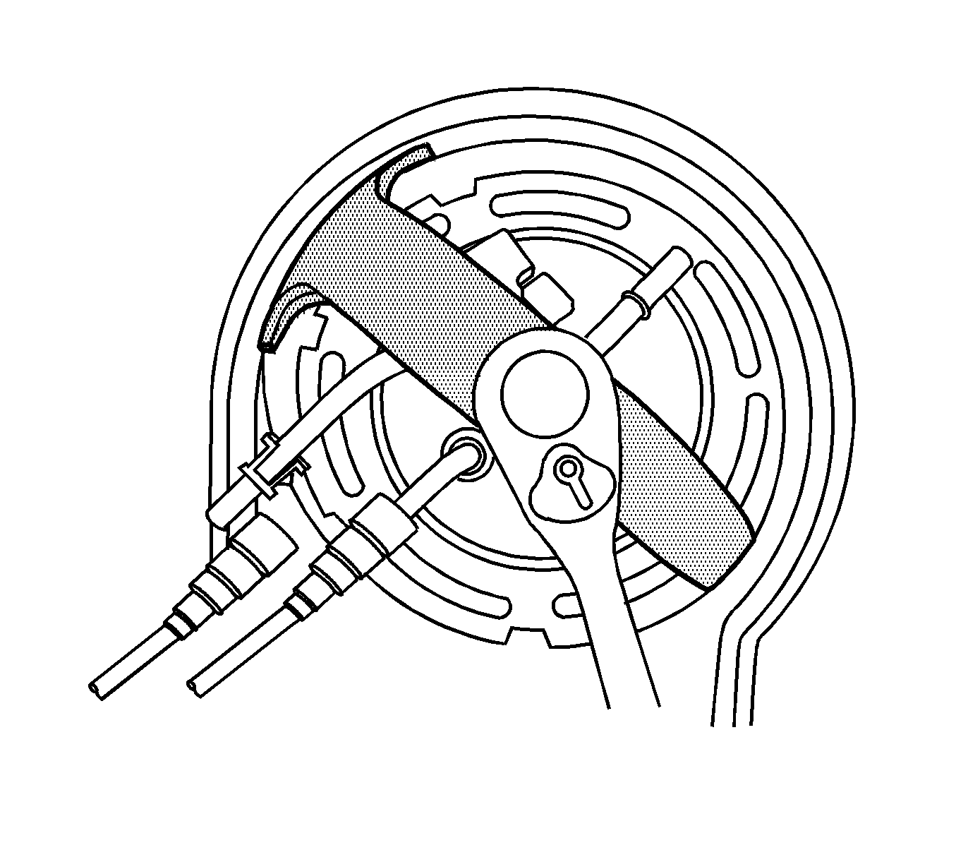
- Using J 45722 , remove the sending unit lock ring.
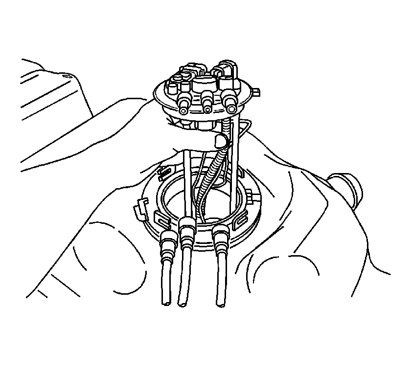
- Remove the sending unit and seal. Discard the seal.
- Clean the sending unit sealing surfaces.
Installation Procedure
- Install the sending unit and a NEW seal.
- Using the J 45722 , install the sending unit lock ring.
- Connect the fuel lines to the sending unit. Refer to Metal Collar Quick Connect Fitting Service or to Plastic Collar Quick Connect Fitting Service .
- Install the fuel tank. Refer to Fuel Tank Replacement .


Fuel Sender Assembly Replacement Rear Tank
Removal Procedure
- Remove the fuel tank. Refer to Fuel Tank Replacement .
- Remove the 6 nuts and washers from the fuel sender assembly retaining ring .
- Remove the fuel sender assembly retaining ring.
- Remove the fuel sender assembly.
- Remove the fuel sender assembly seal from the fuel tank.
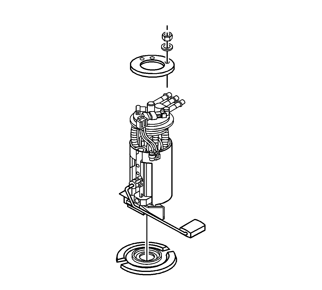
Caution: In order to reduce the risk of fire and personal injury that may result from a fuel leak, always replace the fuel sender gasket when reinstalling the fuel sender assembly.
Installation Procedure
- Install the fuel sender assembly seal to the fuel tank.
- Care should be taken not to fold over or twist the strainer when installing the sender assembly as this will restrict fuel flow.
- Install the fuel sender assembly in the fuel tank.
- Install the fuel sender assembly lock ring to the fuel tank, make sure the lock ring alignment holes fit over the tabs on the tank.
- Install the 6 washers and nuts retaining the fuel sender assembly lock ring.
- Install the fuel tank. Refer to Fuel Tank Replacement .
Notice: Do not fold or twist the strainer when installing the sending unit. This action restricts fuel flow.

Notice: Refer to Fastener Notice in the Preface section.
Tighten
Tighten the lock ring nuts to 11.5 N·m (102 lb in).
Fuel Sender Assembly Replacement Mid Mount Tank
Tools Required
J 44402 Fuel Tank Sending Unit Wrench
Removal Procedure
- Remove the fuel tank. Refer to Fuel Tank Replacement .
- Remove the fuel sender assembly retaining ring using the J 44402 .
- Remove the fuel sender assembly and the seal. Discard the seal.
- Clean the fuel sender sealing surfaces.
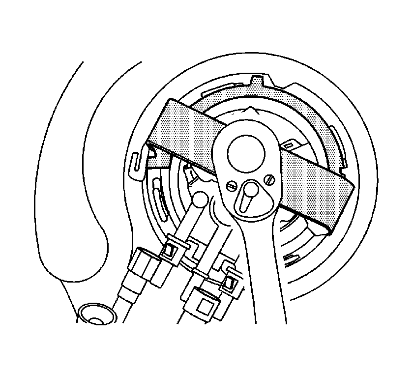
Notice: Do Not handle the fuel sender assembly by the fuel pipes. The amount of leverage generated by handling the fuel pipes could damage the joints.
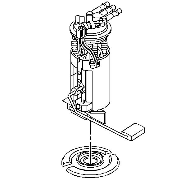
Caution: Drain the fuel from the fuel sender assembly into an approved container in order to reduce the risk of fire and personal injury. Never store the fuel in an open container.
Installation Procedure
- Install the new seal on the fuel tank.
- Install the fuel sender assembly into the fuel tank.
- Install the fuel sender assembly retaining ring using the J 44402 .
- Install the fuel tank. Refer to Fuel Tank Replacement .
Caution: In order to reduce the risk of fire and personal injury that may result from a fuel leak, always replace the fuel sender gasket when reinstalling the fuel sender assembly.
Important: The fuel strainer must be in a horizontal position when the fuel sender is installed in the tank. When installing the fuel sender assembly, assure that the fuel strainer does not block full travel of the float arm.


