Crankshaft main bearings are of the precision insert type and do not utilize shims for adjustment. If the clearances are found to be excessive, a new bearing, both upper and lower inserts will be required. If the clearances are still excessive with the new crankshaft main bearings, the crankshaft must be replaced. No undersize bearings are available for this engine.
The simplest and most accurate way to measure the crankshaft main bearing clearance is the use of plastic gage. This wax-like material compresses evenly between the bearing and the crankshaft journal surfaces.
- Install the upper crankshaft main bearing inserts into the cylinder block.
- Install the crankshaft into the cylinder block.
- Install the upper thrust washer into the cylinder block.
- Install the lower crankshaft bearing inserts into the lower crankcase housing.
- Apply clean engine oil to the crankshaft main bearing and inserts.
- Install the crankshaft into the cylinder block.
- Apply sealant to the sealing surface of the lower crankcase.
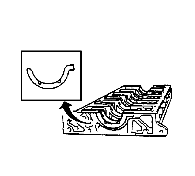
- Install the lower thrust washer half to the lower crankcase housing, with the grooves facing inward.
- Apply a small amount of molybdenum grease to the bolts. (M14 bolts only)
- Install the bolts to the lower crankcase housing.
- Rotate the crankshaft.
- Inspect for burrs on the crankshaft bores, foreign matter between the cylinder block and lower crankcase housing, faulty crankshaft main bearing insert, and repair as necessary.
Important: Upper crankshaft main bearing inserts have the oil holes and grooves in them. Make sure that the bearing inserts fit correctly into the cylinder block.

Important: The upper thrust washer does not have a locating tab. The upper thrust washer must be rolled into the cylinder block. New thrust washers must be used if the crankshaft end play measurement at disassembly was excessive.

Important: Lower crankshaft bearing inserts are plain and have no grooves in them. Make sure that the bearing inserts fit correctly into the cylinder block.

Important: Inspect
the following components for damage. Repair the damage as necessary.
• Burrs on the crankshaft bores • Foreign matter between the cylinder block and the lower crankcase housing • A faulty crankshaft main bearing insert
Tighten
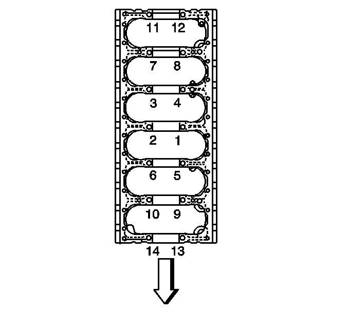
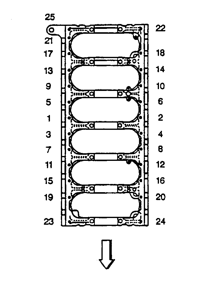
Tighten the bolts in the following steps:
| 10.1. | The bolts marked M14 |
First step: 98 N·m (73 lb ft)
| 10.2. | Second step: 132 N·m (98 lb ft) |
| 10.3. | Turn the bolts an additional 30-60 degrees. |
| Important: Inspect for faulty lower crankcase bolts. Limit the use of the bolts to six times. If a problem is found, replace the bolts as necessary. |
| 10.4. | The bolts marked M10, tighten evenly in sequence. |
Tighten
Tighten the M10 bolts to 37 N·m (27 lb ft).
Important: The crankshaft should rotate freely. If the crankshaft does not rotate freely, loosen the lower crankcase housing bolts (marked M10), until the tight crankshaft main bearing is located.
Measurement Procedure
- Measure the crankshaft for end play.
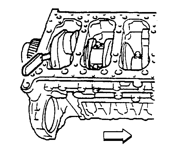
- Tap the crankshaft on the flywheel end with a brass hammer to force it forward.
- Insert a feeler gage between the lower thrust washer half and the crankshaft.
- Production end play is 0.040- 0.205 mm (0.0016-0.0081 in). The service limit is 0.54 mm (0.0213 in)

