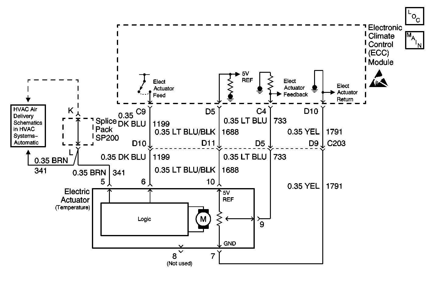
Circuit Description
The HVAC control module receives a position signal from the air temperature actuator. The air temperature actuator position sensor is a potentiometer that is tied to a 5 V reference source. The variable output from the potentiometer feeds back a position signal to a pull-up resistor which is located in the HVAC control module. This signal determines the necessary drive signal to the actuator motor which provides the proper air temperature door position. This value is stored in the Keep Alive Memory (KAM) portion of the HVAC control module.
Conditions for Running the DTC
The ignition is in the ON position.
Conditions for Setting the DTC
With the ignition ON, the HVAC control module will detect this condition any time the signal circuit is near 0 V.
Action Taken When the DTC Sets
The HVAC control module drives the temperature valve to the full COLD position when the system is in one of the following modes:
| • | PANEL |
| • | BI-LEVEL |
| • | AUTO PANEL/AUTO BI-LEVEL |
The HVAC control module drives the temperature valve to full HEAT position when the system is in one of the following modes:
| • | LOWER |
| • | DEFOG |
| • | DEFROST |
| • | AUTO LOWER |
Conditions for Clearing the DTC
| • | The DTC becomes history when the HVAC control module no longer detects a failure. |
| • | The history DTC clears after 50 fault-free ignition cycles. |
| • | The DTC can be cleared with a scan tool. |
Diagnostic Aids
| • | Normal operating range is 40 Counts to 200 Counts. If out of this range check for binding, misalignment, or broken air temperature door. |
| • | If condition is not present refer to Testing for Intermittent Conditions and Poor Connections in Wiring Systems. |
Test Description
The number(s) below refer to the step number(s) on the diagnostic table.
-
Tests for the proper operation of the circuit in the high voltage range.
-
Tests for the proper operation of the circuit in the low voltage range. If the fuse in the jumper opens when you perform this test, the signal circuit is shorted to voltage.
-
Tests for a short to ground in the 5 volt reference circuit.
Step | Action | Value(s) | Yes | No |
|---|---|---|---|---|
1 | Did you perform the HVAC Diagnostic System Check? | -- | Go to Step 2 | Go to Diagnostic System Check |
2 |
Does the voltage measure within the specified range? | 0.09-4.95 V | Go to Diagnostic Aids | Go to Step 3 |
Does the voltage measure greater than the specified value? | 4.95 V | Go to Step 4 | Go to Step 8 | |
Does the voltage measure less than the specified value? | 0.09 V | Go to Step 5 | Go to Step 9 | |
Does the voltage measure greater than the specified value? | 4.95 V | Go to Step 7 | Go to Step 6 | |
6 | Test the 5 volt reference circuit of the air temperature actuator for a short to ground. Refer to Circuit Testing and Wiring Repairs in Wiring Systems. Did you find and correct the condition? | -- | Go to Step 15 | Go to Step 12 |
7 | Test the 5 volt reference circuit of the air temperature actuator for a [short to voltage, a high resistance, or an open]. Refer to Circuit Testing and Wiring Repairs in Wiring Systems. Did you find and correct the condition? | -- | Go to Step 15 | Go to Step 11 |
8 | Test the signal circuit of the air temperature actuator for a short to ground. Refer to Circuit Testing and Wiring Repairs in Wiring Systems. Did you find and correct the condition? | -- | Go to Step 15 | Go to Step 12 |
9 | Test the signal circuit of the air temperature actuator for a short to voltage, a high resistance, or an open. Refer to Circuit Testing and Wiring Repairs in Wiring Systems. Did you find and correct the condition? | -- | Go to Step 15 | Go to Step 10 |
10 | Test the low reference circuit of the air temperature actuator for a high resistance or an open. Refer to Circuit Testing and Wiring Repairs in Wiring Systems. Did you find and correct the condition? | -- | Go to Step 15 | Go to Step 12 |
11 | Inspect for poor connections at the harness connector of the air temperature actuator. Refer to Testing for Intermittent Conditions and Poor Connections and Special Tools in Wiring Systems. Did you find and correct the condition? | -- | Go to Step 15 | Go to Step 13 |
12 | Inspect for poor connections at the harness connector of the HVAC control module. Refer to Testing for Intermittent Conditions and Poor Connections and Special Tools in Wiring Systems. Did you find and correct the condition? | -- | Go to Step 15 | Go to Step 14 |
13 |
Important: Perform the recalibration procedure for the air temperature actuator. Replace the air temperature actuator. Refer to Temperature Actuator Replacement . Did you complete the replacement? | -- | Go to Step 15 | -- |
14 | Replace the HVAC control module. Refer to Control Assembly Replacement . Did you complete the replacement? | -- | Go to Step 15 | -- |
15 |
Does the DTC reset? | -- | Go to Step 2 | System OK |
