Tools Required
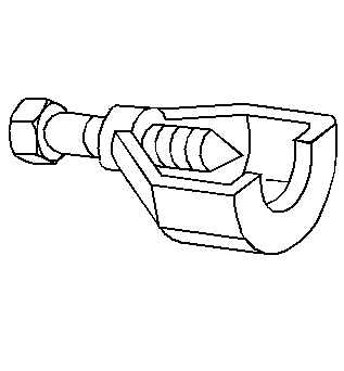
| • | J 5825-A Crankshaft Gear Remover |
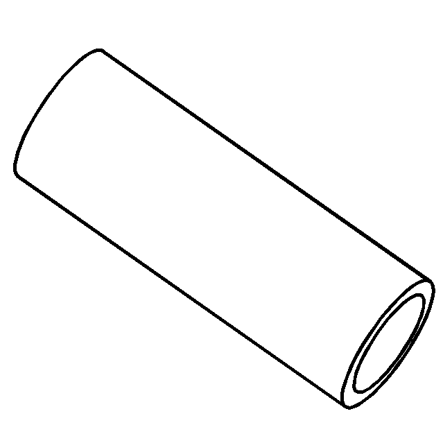
| • | J 5590 Crankshaft Gear Installer |
Removal Procedure
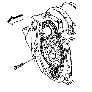
- Remove the engine front cover. Refer to Engine Front Cover Replacement .
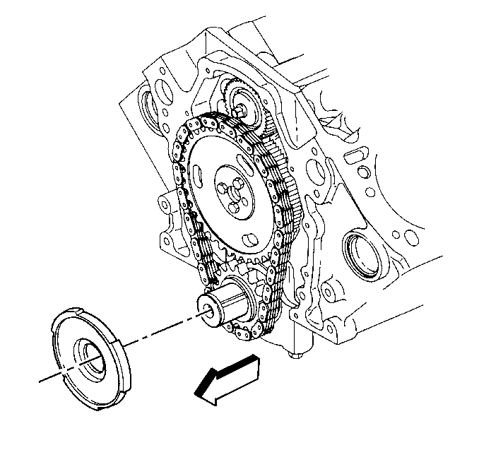
- Remove the crankshaft position sensor reluctor ring.
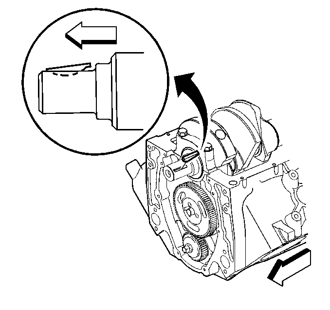
- Install a 7/16-20 x 1 inch bolt into the end of the crankshaft.
- Rotate the crankshaft until:
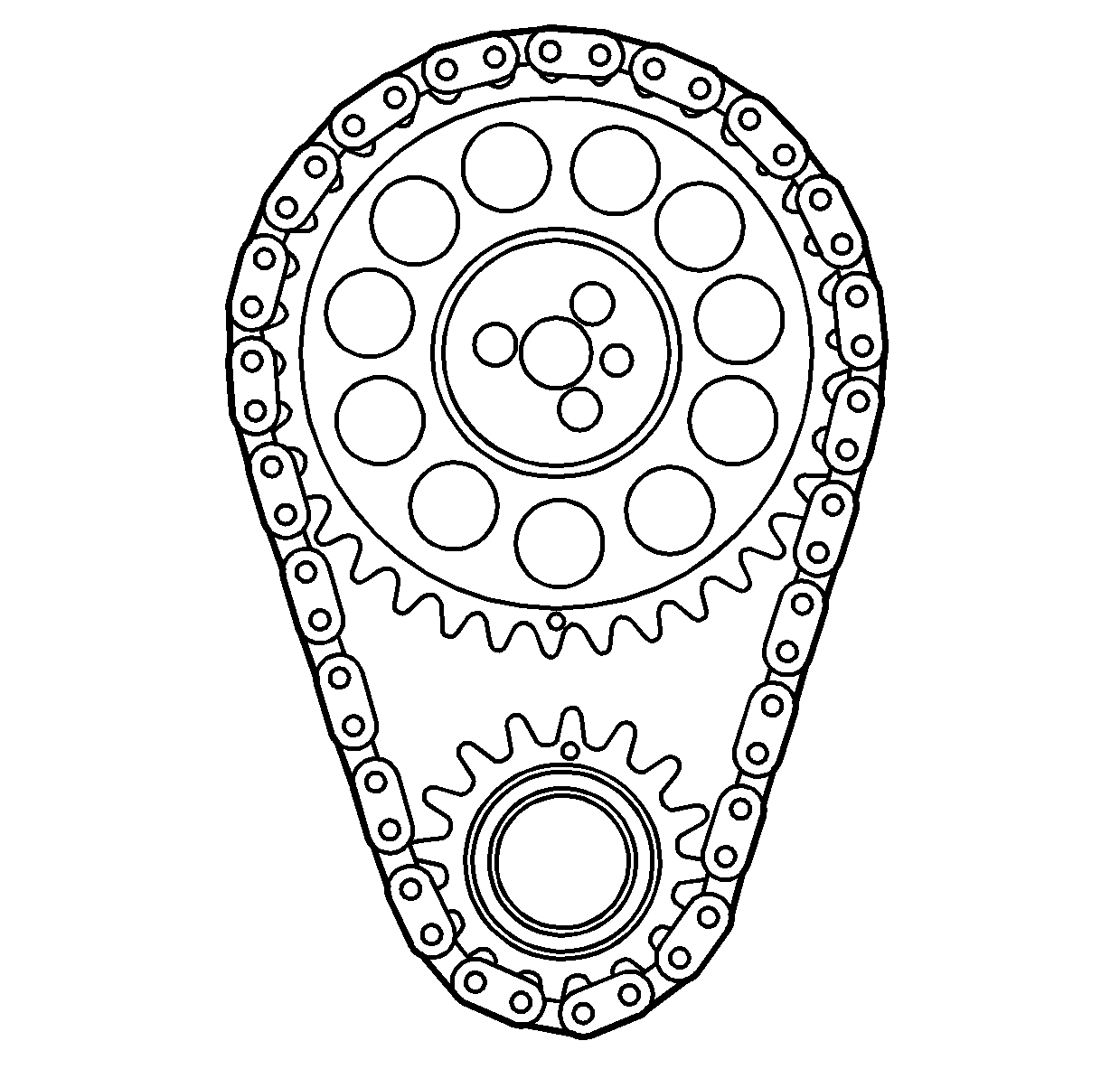
- Remove the camshaft sprocket bolts.
- Remove the camshaft sprocket and the camshaft timing chain.
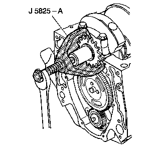
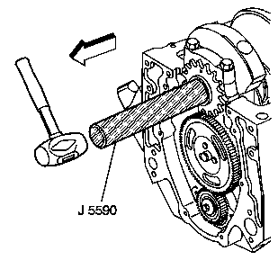
- Remove the crankshaft sprocket using theJ 5825-A .
- Remove the crankshaft balancer key.
- Clean the components with cleaning solvent.
- Dry the components with compressed air.
- Inspect the camshaft timing chain for binding or wear.
- Inspect the camshaft sprocket and the crankshaft sprocket for:
Notice: In order to rotate the engine install a bolt with the same threads as the crankshaft, but do not use the crankshaft balancer bolt or a bolt longer than 1 inch, in the crankshaft. Failing to do so will cause damage to the bolt threads and the crankshaft threaded hole when removing the bolt.
Notice: Align the timing marks before removing the timing chain. If it is necessary to turn either the camshaft or the crankshaft with the timing chain removed, loosen or remove the valve rocker arms. Turning either the crankshaft or camshaft with the timing chain removed may cause the pistons to contact the valves, resulting in damage.
| 4.1. | The timing marks on both sprockets line up. |
| 4.2. | The number four cylinder is at top dead center (TDC) of the compression stroke. |
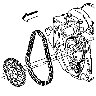
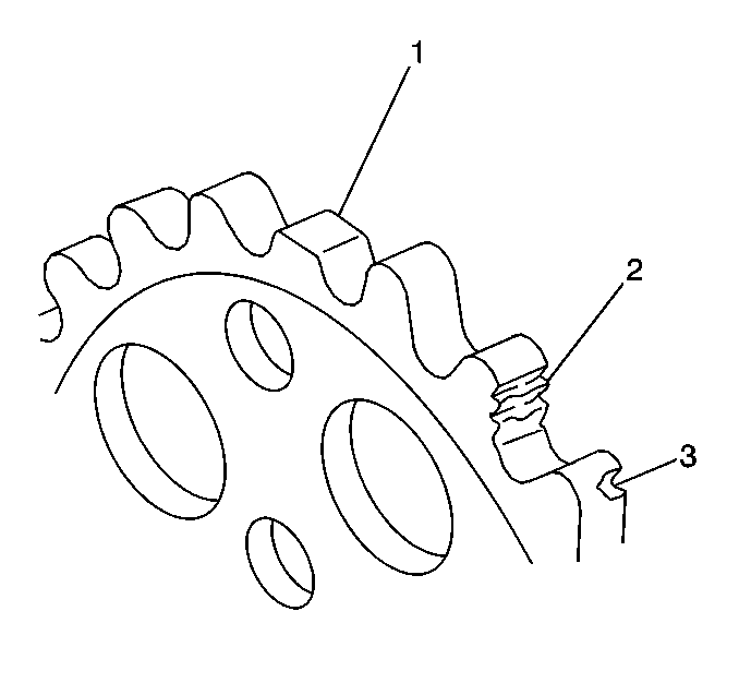
| • | Broken teeth (1) |
| • | Damaged teeth (2) |
| • | Chipped teeth (3) |
| • | Worn teeth |
| • | Uneven wear on the edge of the teeth |
| • | Worn valleys between the sprocket teeth |
| • | Crankshaft sprocket keyway for wear |
Installation Procedure
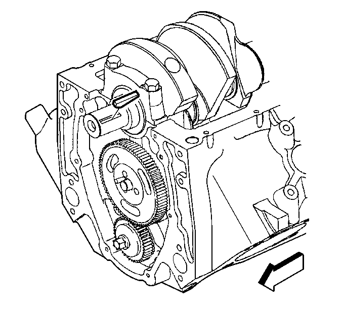
- Install the crankshaft balancer key into the crankshaft keyway.
- Align the keyway of the crankshaft sprocket with the crankshaft balancer key.
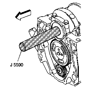
- Use theJ 5590 in order to install the crankshaft sprocket.
- Install the camshaft sprocket and the camshaft timing chain.
- Look to ensure that the crankshaft sprocket is aligned at the 12 o'clock position and camshaft sprocket is aligned at the 6 o'clock position.
- Install camshaft sprocket bolts.
- Install the crankshaft position sensor reluctor ring.
The crankshaft balancer key should be parallel to the crankshaft or with a slight incline.
Important: Install the camshaft sprocket with the alignment mark at the 6 o'clock position.
Notice: Use the correct fastener in the correct location. Replacement fasteners must be the correct part number for that application. Fasteners requiring replacement or fasteners requiring the use of thread locking compound or sealant are identified in the service procedure. Do not use paints, lubricants, or corrosion inhibitors on fasteners or fastener joint surfaces unless specified. These coatings affect fastener torque and joint clamping force and may damage the fastener. Use the correct tightening sequence and specifications when installing fasteners in order to avoid damage to parts and systems.
Important: Do not use a hammer to install the camshaft sprocket onto the camshaft. To do so may dislodge the expansion cup plug (camshaft rear bearing hole).
Tighten
Tighten the camshaft sprocket bolts to 25 N·m (18 lb ft).
| 7.1. | Align the keyway on the crankshaft position sensor reluctor ring with the crankshaft balancer key in the crankshaft. |
| 7.2. | Use theJ 5590 in order to push the crankshaft position sensor reluctor ring onto the crankshaft until completely seated against the crankshaft sprocket. |
| 7.3. | Remove the bolt that was installed in the end of the crankshaft. |
| 7.4. | Install the engine front cover. Refer to Engine Front Cover Replacement . |
