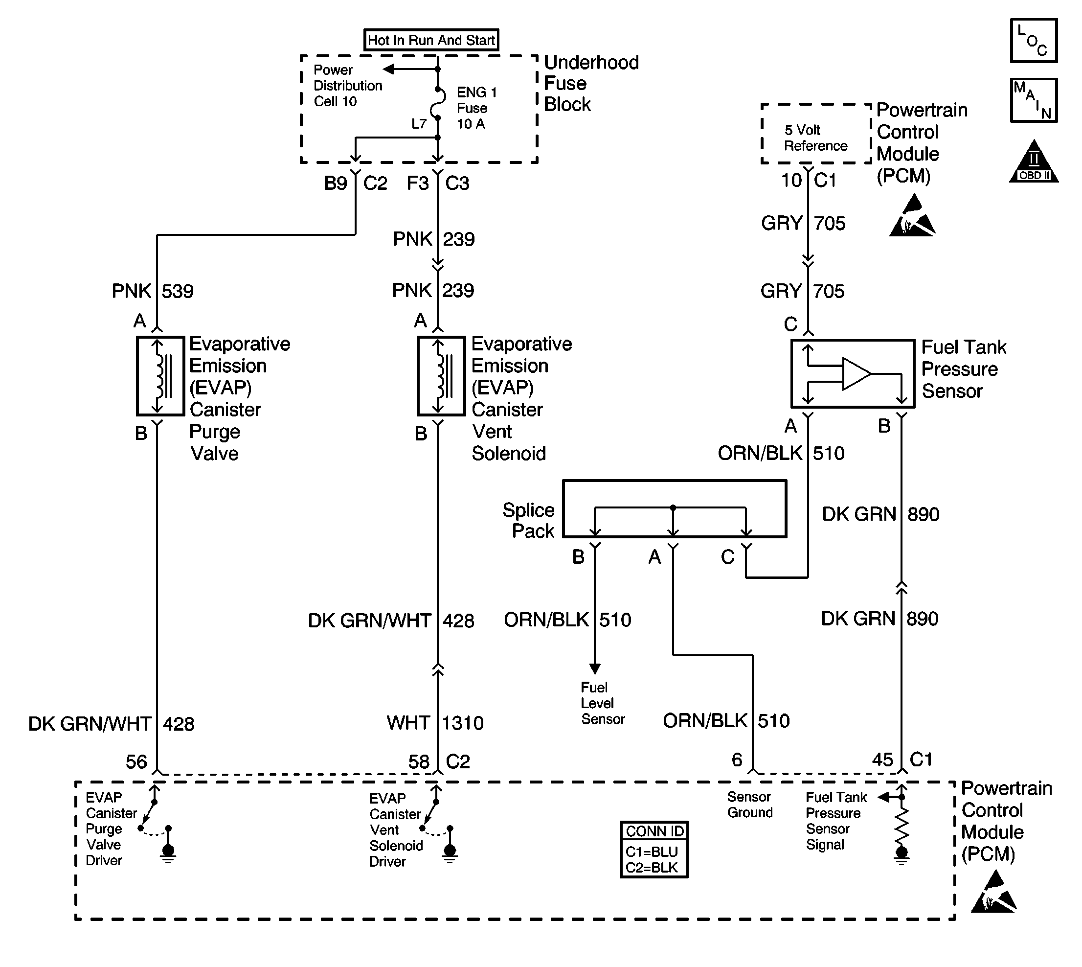
System Description
The EVAP large leak test is based on applying vacuum to the evaporative emission (EVAP) system and monitoring vacuum decay. The powertrain control module (PCM) uses the input from the fuel tank pressure sensor to determine the rate of vacuum decay. At an appropriate time, the PCM commands the EVAP canister purge valve, and the EVAP vent valve ON. This opens the purge valve, and closes the vent valve. This allows engine vacuum to be applied on the EVAP system. At a calibrated time or vacuum level, the PCM turns the purge valve OFF, and monitors the EVAP system vacuum. If the system is unable to achieve, or maintain a calibrated vacuum level, the PCM will set DTC P0440.
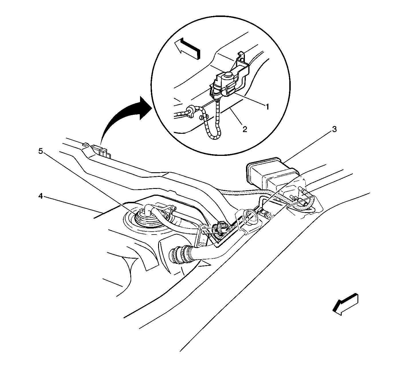
The EVAP system includes the following components:
| • | The fuel tank |
| • | The EVAP canister vent valve |
| • | The fuel pipes and hoses |
| • | The fuel fill cap |
| • | The EVAP vapor pipes |
| • | The EVAP purge pipes |
| • | The EVAP canister |
| • | The EVAP purge valve |
Conditions for Running the DTC
| • | TP, IAT, FTP, ECT or MAP sensor DTCs are not set. |
| • | System voltage is between 10-18 volts. |
| • | Startup ECT is not more than 4°-30°C (39-86°F). |
| • | Startup ECT is not more than 8°C (14°F) more than IAT startup temperature. |
| • | Startup IAT not more than 4-30°C (39- 86°F). |
| • | Fuel tank level is between 15-85 percent. |
| • | BARO is more than 75kPa. |
| • | IAT is less than 30°C (86°F). |
| • | TPS between 7-35 percent. |
| • | VSS below 129 km/h (80 mph). |
Conditions For Setting the DTC
The EVAP System is not able to achieve or maintain vacuum during the diagnostic test.
Action Taken When the DTC Sets
| • | The PCM will illuminate the malfunction indicator lamp (MIL) during the second consecutive trip in which the diagnostic test has been run and failed. |
| • | The PCM will store conditions which were present when the DTC set as Freeze Frame/Failure Records data. |
Conditions for Clearing the MIL/DTC
| • | The PCM will turn the MIL OFF during the first consecutive trip in which the diagnostic has been run and Passed. |
| • | A last test failed (current DTC) clears when the PCM turns OFF the MIL. |
| • | The history DTC will clear after the PCM runs and passes 40 consecutive warm up cycles with no failure. |
| • | The DTC can be cleared by using a scan tool. |
Diagnostic Aids
Important: If charcoal release is detected, replace the EVAP canister. Refer to Evaporative Emission Canister Replacement .
The following conditions will set DTC P0440:
| • | An open ignition feed circuit to the EVAP vent or purge valve. |
| • | A fuel fill cap that is missing, improperly installed or malfunctioning. |
| • | Disconnected, damaged, pinched, or blocked conditions of one or more of the following components: |
| - | The fuel tank vapor line |
| - | The EVAP purge line |
| • | Malfunction of one or more of the following components: |
| - | The EVAP canister purge valve |
| - | An EVAP vent valve |
| • | Damage or disconnected condition of one or more of the following components: |
| - | The EVAP canister |
| - | An EVAP vent hose |
| • | A leak in or from one of the following components: |
| - | The fuel sender assembly O-ring |
| - | The fuel tank |
| - | The fuel filler neck |
Reviewing the Fail Records vehicle mileage since the diagnostic test last failed may help determine how often the condition that caused the DTC to be set occurs. This may assist in diagnosing the condition.
If the condition is intermittent refer to Intermittent Conditions .
Test Description
The numbers below refer to the step numbers on the diagnostic table.
-
This test verifies that the EVAP purge valve can be commanded ON and OFF.
-
This test verifies that the EVAP vent valve can be commanded ON and OFF.
-
Refer to the information supplied with the EVAP pressure/purge diagnostic cart on proper setup and adjustment procedures.
-
With pressure applied it may be necessary to disconnect the EVAP lines at the components to verify that a line or component is not restricted. A restriction would prevent a vacuum (or the step 9 test pressure) from forming in the fuel tank.
-
An EVAP pressure sensor that does not correctly respond to vacuum (or pressure) will cause this DTC to set.
Step | Action | Values | Yes | No | ||||||||
|---|---|---|---|---|---|---|---|---|---|---|---|---|
1 | Did you perform the Powertrain On-board Diagnostic (OBD) System check? | -- | ||||||||||
2 | Are DTCs P0446, P0452, P0453, P0461, P0462, P0463, P1441 set? | -- | Go to Applicable DTC | |||||||||
3 | Inspect the EVAP system for the following conditions:
Repair the EVAP system if needed. Did you find and correct the condition? | -- | ||||||||||
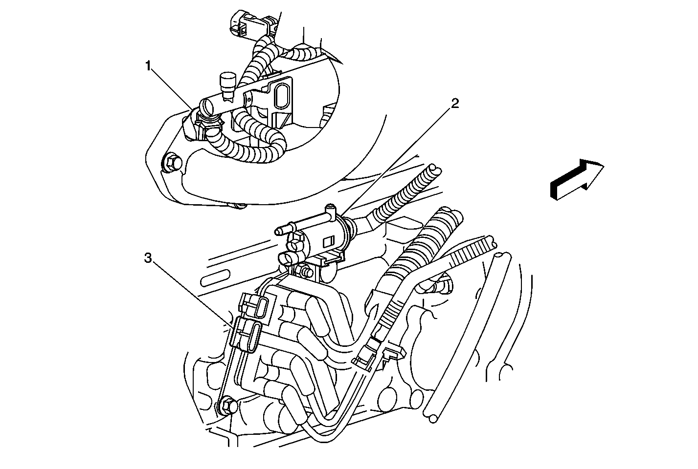
Command the EVAP purge valve ON and OFF with the scan tool. Refer to
Do you hear an audible click as the EVAP purge valve is commanded ON and OFF? | -- | |||||||||||
Command the EVAP purge vent
valve ON and OFF with the scan tool. Refer to
Do you hear an audible click as the EVAP vent valve is commanded ON and OFF? | -- | |||||||||||
6 |
Is the vacuum at or above the specified value? | 12 in Hg | ||||||||||
7 |
Can the specified value be obtained and held? | 5 in Hg | ||||||||||
8 |
Can the specified value be obtained and held? | 5 in Hg | ||||||||||
9 |
Did you find and correct the condition? | -- | ||||||||||
|
Important: The following steps require the EVAP pressure/purge diagnostic station J 41413 and the ultrasonic leak detector J 41416 . Always zero the EVAP pressure and vacuum (in. H2O) gauges on the EVAP pressure/purge diagnostic station before proceeding with diagnosis.
Important: Do Not apply more than 15 inches H2O of pressure to the EVAP system. Did you find and correct the condition? | -- | |||||||||||
Inspect the EVAP system for restrictions. Refer to test description. Did you find and correct the condition? | -- | |||||||||||
12 |
Does the test lamp illuminate? | -- | ||||||||||
13 |
Does the test lamp illuminate when the EVAP purge valve is commanded ON? | -- | ||||||||||
14 | Test the EVAP purge valve control circuit for an open or short to B+. Refer to Circuit Testing and Wiring Repairs in Wiring Systems. Did you find and correct the condition? | -- | ||||||||||
15 |
Is the test lamp illuminated? | -- | ||||||||||
16 |
Does the test lamp illuminate when the EVAP vent valve is commanded ON? | -- | ||||||||||
17 | Test the EVAP vent valve control circuit for an open or short to B+. Refer to Circuit Testing and Wiring Repairs in Wiring Systems. Did you find and correct the condition? | -- | ||||||||||
18 | Repair the EVAP purge valve ignition voltage circuit for an open or short to ground. Refer to Wiring Repairs in Wiring Systems. Is the repair complete? | -- | -- | |||||||||
19 | Repair the EVAP vent valve ignition voltage circuit for an open or short to ground. Refer to Wiring Repairs in Wiring Systems. Is the repair complete? | -- | -- | |||||||||
20 | Inspect the vacuum source to the EVAP purge valve for damage or a disconnect. Did you find and correct the condition? | -- | ||||||||||
21 |
Important:
Replace the EVAP purge valve. Refer to Evaporative Emission Canister Purge Solenoid Valve Replacement . Is the replacement complete? | -- | -- | |||||||||
22 |
Important: Inspect for poor connections at the harness connector of the EVAP vent valve. Replace the EVAP vent valve. Refer to Evaporative Emission Vent Valve Replacement . Is the replacement complete? | -- | -- | |||||||||
23 | Replace the EVAP vapor canister. Refer to Evaporative Emission Canister Replacement . Is the replacement complete? | -- | -- | |||||||||
Does the EVAP pressure/purge diagnostic station vacuum gauge reading correspond to the fuel tank pressure sensor value displayed on the scan tool ? | -- | Go to Intermittent Conditions | ||||||||||
25 | Replace the fuel tank pressure sensor. Refer to Fuel Tank Pressure Sensor Replacement . Did you complete the replacement? | -- | -- | |||||||||
26 |
Important: Inspect for poor connections at the harness connector of the PCM. Replace the PCM. Refer to Powertrain Control Module Replacement/Programming . Did you complete the replacement? | -- | -- | |||||||||
27 |
Does the EVAP system pressure stay constant? | 10 in Hg | ||||||||||
28 | With a scan tool, observe the stored information, Capture Info. Does the scan tool display any DTCs that you have not diagnosed? | -- | Go to applicable DTC | System OK |
