DTC P1860 TCC PWM Solenoid Circuit Electrical 2.2L
Circuit Description
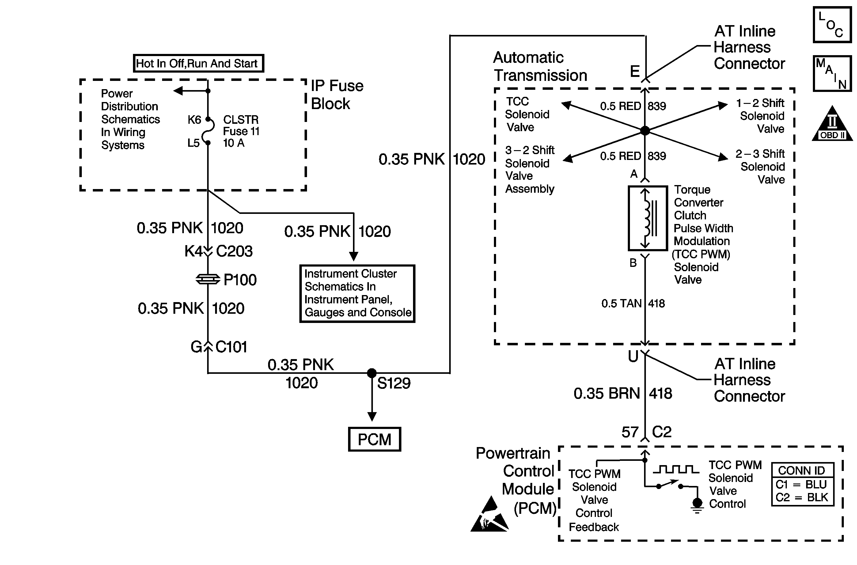
The torque converter clutch pulse width modulation (TCC PWM) solenoid valve controls the fluid acting on the converter clutch valve. The converter clutch valve controls the TCC application and release. The solenoid attaches to the control valve body within the transmission. The solenoid receives ignition voltage through circuit 1020. The powertrain control module (PCM) controls the solenoid by providing a ground path on circuit 418. Current flows through the solenoid coil according to the duty cycle (percentage of ON and OFF time). The TCC PWM solenoid valve provides a smooth engagement of the torque converter clutch by operating during a duty cycle percent of ON time.
When the PCM detects a continuous open, short to ground or short to power in the TCC PWM solenoid valve circuit, then DTC P1860 sets. DTC P1860 is a type B DTC.
Conditions for Running the DTC
| • | The system voltage is 10-18 volts. |
| • | The TCC duty cycle is less than 10% or greater than 90%. |
Conditions for Setting the DTC
DTC P1860 sets if one of the following conditions occurs for 5 seconds:
Condition 1
The PCM commands the solenoid ON (90%) and the voltage feedback remains high (B+).
Condition 2
The PCM commands the solenoid OFF (0%) and the voltage feedback remains low (0 volt).
Action Taken When the DTC Sets
| • | The PCM illuminates the malfunction indicator lamp (MIL) during the second consecutive trip in which the Conditions for Setting the DTC are met. |
| • | The PCM inhibits TCC engagement. |
| • | The PCM inhibits 4th gear if the transmission is in hot mode. |
| • | The PCM freezes shift adapts from being updated. |
| • | The PCM records the operating conditions when the Conditions for Setting the DTC are met. The PCM stores this information as Freeze Frame and Failure Records. |
| • | The PCM stores DTC P1860 in PCM history during the second consecutive trip in which the Conditions for Setting the DTC are met. |
Conditions for Clearing the MIL/DTC
| • | The PCM turns OFF the MIL during the third consecutive trip in which the diagnostic test runs and passes. |
| • | A scan tool can clear the MIL/DTC. |
| • | The PCM clears the DTC from PCM history if the vehicle completes 40 warm-up cycles without an emission-related diagnostic fault occurring. |
| • | The PCM cancels the DTC default actions when the fault no longer exists and/or the ignition switch is OFF long enough in order to power down the PCM. |
Diagnostic Aids
| • | Inspect the connectors at the PCM, the TCC PWM solenoid valve and all other circuit connecting points for an intermittent condition. Refer to Testing for Intermittent Conditions and Poor Connections in Wiring Systems. |
| • | Inspect the circuit wiring for an intermittent condition. Refer to Testing for Electrical Intermittents in Wiring Systems. |
| • | A faulty ignition switch may set this code. |
Test Description
The numbers below refer to the step numbers on the diagnostic table.
-
This step tests for voltage to the solenoid.
-
This step tests the ability of the PCM and wiring to control the ground circuit.
-
This step tests the resistance of the TCC PWM solenoid valve and the automatic transmission (AT) wiring harness assembly.
Step | Action | Value(s) | Yes | No | ||||||||
|---|---|---|---|---|---|---|---|---|---|---|---|---|
1 | Did you perform the Powertrain Diagnostic System Check? | -- | Go to Powertrain On Board Diagnostic (OBD) System Check (2.2L) in Engine Controls | |||||||||
2 |
Important: Before clearing the DTC, use the Scan Tool in order to record the Freeze Frame and Failure Records. Using the Clear Info function erases the Freeze Frame and Failure Records from the PCM. Are any of the following DTCs also set?
| -- | ||||||||||
3 | Inspect the CLSTR fuse for an open. Refer to General Electrical Diagnosis in Wiring Systems. Is the fuse open? | -- | ||||||||||
Refer to Automatic Transmission Inline Harness Connector End View . Does the test lamp illuminate? | -- | |||||||||||
Refer to Automatic Transmission Inline Harness Connector End View . Does the test lamp turn ON and OFF with each command? | -- | |||||||||||
6 | Is the test lamp always ON? | -- | ||||||||||
Refer to Automatic Transmission Inline Harness Connector End View . Does the resistance measure within the specified range? | 10-15 ohms | |||||||||||
8 | Measure the resistance from terminal E to ground, and from terminal U to ground. Do both readings measure greater than the specified value? | 250 K ohms | Go to Diagnostic Aids | |||||||||
9 |
Does the resistance measure within the specified range? | 10-15 ohms | ||||||||||
10 |
Do both readings measure greater than the specified value? | 250 K ohms | ||||||||||
11 |
Important: The condition that affects this circuit may exist in other connecting branches of the circuit. Refer to Power Distribution Schematics in Wiring Systems for complete circuit distribution. Test the power feed circuit (CKT 1020) of the TCC PWM solenoid valve for a short to ground between the IP fuse block and the AT inline 20-way connector. Refer to Circuit Testing and Wiring Repairs in Wiring Systems. Did you find and correct the condition? | -- | ||||||||||
12 |
Important: The condition that affects this circuit may exist in other connecting branches of the circuit. Refer to Power Distribution Schematics in Wiring Systems for complete circuit distribution. Test the power feed circuit (CKT 839) of the TCC PWM solenoid valve for a short to ground between the AT inline 20-way connector and the TCC PWM solenoid valve. Refer to Circuit Testing in Wiring Systems. Did you find a short to ground condition? | -- | ||||||||||
13 |
Did you complete the replacement? | -- | -- | |||||||||
14 |
Important: The condition that affects this circuit may exist in other connecting branches of the circuit. Refer to Power Distribution Schematics in Wiring Systems for complete circuit distribution. Test the power feed circuit (CKT 1020) of the TCC PWM solenoid valve for an open. Refer to Circuit Testing and Wiring Repairs in Wiring Systems. Did you find and correct the condition? | -- | -- | |||||||||
15 | Test the control circuit (CKT 418) of the TCC PWM solenoid valve for a short to ground between the PCM connector C2 and the AT inline 20-way connector. Refer to Circuit Testing and Wiring Repairs in Wiring Systems. Did you find and correct the condition? | -- | ||||||||||
16 | Test the control circuit (CKT 418) of the TCC PWM solenoid valve for an open or short to power between the PCM connector C2 and the AT inline 20-way connector. Refer to Circuit Testing and Wiring Repairs in Wiring Systems. Did you find and correct the condition? | -- | ||||||||||
17 | Replace the AT wiring harness assembly. Refer to Valve Body . Did you complete the replacement? | -- | -- | |||||||||
18 | Replace the TCC PWM Solenoid valve. Refer to Valve Body . Did you complete the replacement? | -- | -- | |||||||||
19 | Replace the PCM. Refer to Powertrain Control Module Replacement/Programming in Engine Controls. Did you complete the replacement? | -- | -- | |||||||||
20 | Perform the following procedure in order to verify the repair:
Has the test run and passed? | -- | System OK |
DTC P1860 TCC PWM Solenoid Circuit Electrical 4.3L
Circuit Description
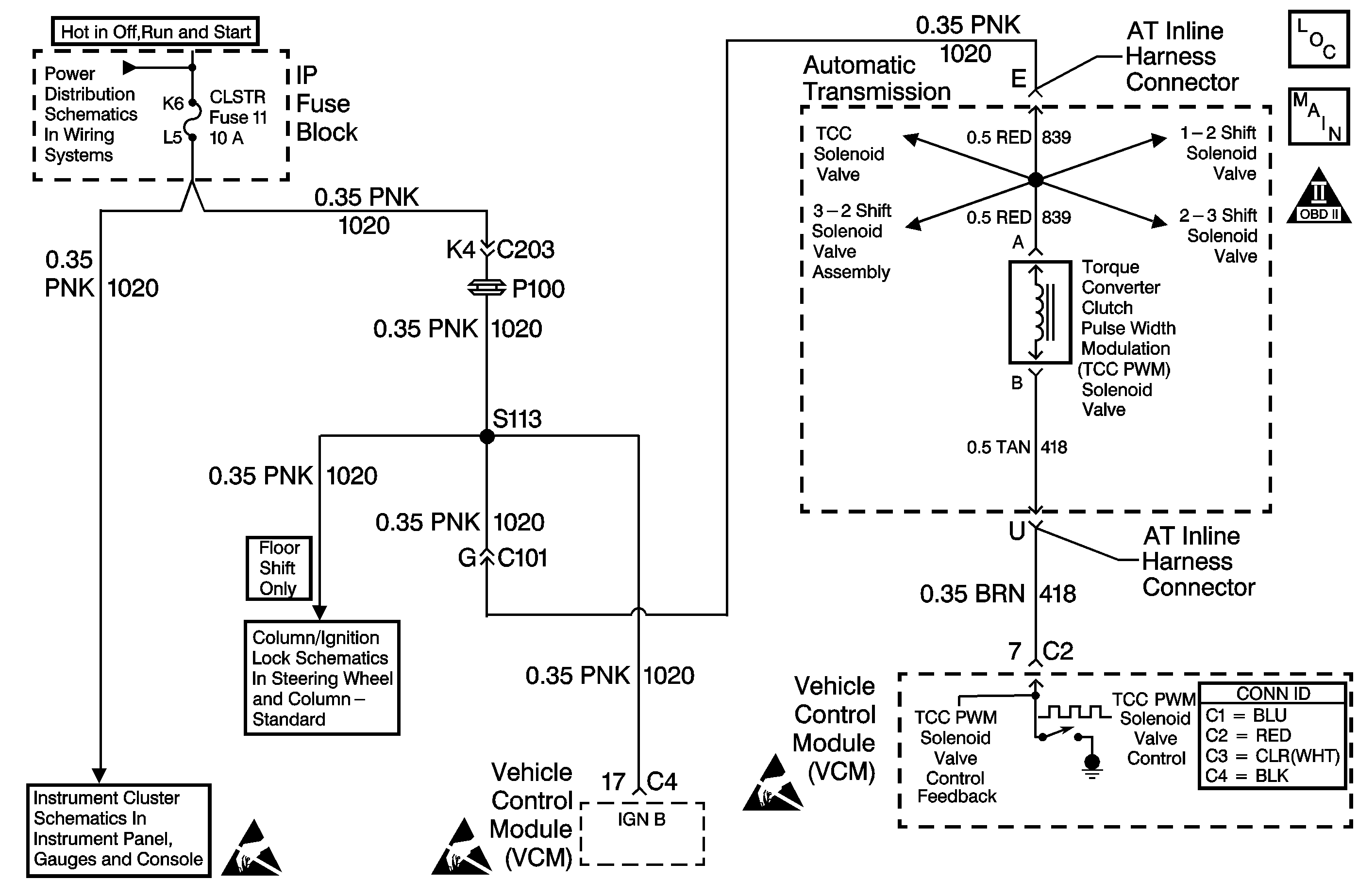
The torque converter clutch pulse width modulation (TCC PWM) solenoid valve controls the fluid acting on the converter clutch valve. The converter clutch valve controls the TCC application and release. The solenoid attaches to the control valve body within the transmission. The solenoid receives ignition voltage through circuit 1020. The vehicle control module (VCM) controls the solenoid by providing a ground path on circuit 418. Current flows through the solenoid coil according to the duty cycle (percentage of ON and OFF time). The TCC PWM solenoid valve provides a smooth engagement of the TCC by operating during a duty cycle percent of ON time.
When the VCM detects a continuous open, short to ground or short to power in the TCC PWM solenoid valve circuit, then DTC P1860 sets. DTC P1860 is a type A DTC.
Conditions for Running the DTC
| • | The system voltage is 10-19 volts. |
| • | The engine speed is greater than 450 RPM for 5 seconds. |
| • | The engine is not in fuel cutoff. |
| • | The VCM commands first gear. |
| • | The TCC duty cycle is less than 10% or greater than 90%. |
Conditions for Setting the DTC
DTC P1860 sets if one of the following conditions occurs for 5 seconds:
Condition 1
The VCM commands the solenoid ON (90%) and the voltage feedback remains high (B+).
Condition 2
The VCM commands the solenoid OFF (0%) and the voltage feedback remains low (0 volt).
Action Taken When the DTC Sets
| • | The VCM illuminates the malfunction indicator lamp (MIL). |
| • | The VCM inhibits TCC engagement. |
| • | The VCM inhibits 4th gear if the transmission is in hot mode. |
| • | The VCM freezes shift adapts from being updated. |
| • | The VCM records the operating conditions when the Conditions for Setting the DTC are met. The VCM stores this information as Freeze Frame and Failure Records. |
| • | The VCM stores DTC P1860 in VCM history. |
Conditions for Clearing the MIL/DTC
| • | The VCM turns OFF the MIL during the third consecutive trip in which the diagnostic test runs and passes. |
| • | A scan tool can clear the MIL/DTC. |
| • | The VCM clears the DTC from VCM history if the vehicle completes 40 warm-up cycles without an emission-related diagnostic fault occurring. |
| • | The VCM cancels the DTC default actions when the fault no longer exists and/or the ignition switch is OFF long enough in order to power down the VCM. |
Diagnostic Aids
| • | Inspect the connectors at the VCM, the TCC PWM solenoid valve and all other circuit connecting points for an intermittent condition. Refer to Testing for Intermittent Conditions and Poor Connections in Wiring Systems. |
| • | Inspect the circuit wiring for an intermittent condition. Refer to Testing for Electrical Intermittents in Wiring Systems. |
| • | A faulty ignition switch may set this code. |
Test Description
The numbers below refer to the step numbers on the diagnostic table.
-
This step tests for voltage to the solenoid.
-
This step tests the ability of the VCM and wiring to control the ground circuit.
-
This step tests the resistance of the TCC PWM solenoid valve and the automatic transmission (AT) wiring harness assembly.
Step | Action | Value(s) | Yes | No | ||||||||
|---|---|---|---|---|---|---|---|---|---|---|---|---|
1 | Did you perform the Powertrain Diagnostic System Check? | -- | Go to Powertrain On Board Diagnostic (OBD) System Check (4.3L) in Engine Controls | |||||||||
2 |
Important: Before clearing the DTC, use the Scan Tool l in order to record the Freeze Frame and Failure Records. Using the Clear Info function erases the Freeze Frame and Failure Records from the VCM. Are any of the following DTCs also set?
| -- | ||||||||||
3 | Inspect the CLSTR fuse for an open. Refer to General Electrical Diagnosis in Wiring Systems. Is the fuse open? | -- | ||||||||||
Refer to Automatic Transmission Inline Harness Connector End View . Does the test lamp illuminate? | -- | |||||||||||
Refer to Automatic Transmission Inline Harness Connector End View . Does the test lamp turn ON and OFF with each command? | -- | |||||||||||
6 | Is the test lamp always ON? | -- | ||||||||||
Refer to Automatic Transmission Inline Harness Connector End View . Does the resistance measure within the specified range? | 10-15 ohms | |||||||||||
8 | Measure the resistance from terminal E to ground, and from terminal U to ground. Do both readings measure greater than the specified value? | 250 K ohms | Go to Diagnostic Aids | |||||||||
9 |
Does the resistance measure within the specified range? | 10-15 ohms | ||||||||||
10 |
Do both readings measure greater than the specified value? | 250 K ohms | ||||||||||
11 |
Important: The condition that affects this circuit may exist in other connecting branches of the circuit. Refer to Power Distribution Schematics in Wiring Systems for complete circuit distribution. Test the power feed circuit (CKT 1020) of the TCC PWM solenoid valve for a short to ground between the IP fuse block and the AT inline 20-way connector. Refer to Circuit Testing and Wiring Repairs in Wiring Systems. Did you find and correct the condition? | -- | ||||||||||
12 |
Important: The condition that affects this circuit may exist in other connecting branches of the circuit. Refer to Power Distribution Schematics in Wiring Systems for complete circuit distribution. Test the power feed circuit (CKT 839) of the TCC PWM solenoid valve for a short to ground between the AT inline 20-way connector and the TCC PWM solenoid valve. Refer to Circuit Testing in Wiring Systems. Did you find a short to ground condition? | -- | ||||||||||
13 |
Did you complete the replacement? | -- | -- | |||||||||
14 |
Important: The condition that affects this circuit may exist in other connecting branches of the circuit. Refer to Power Distribution Schematics in Wiring Systems for complete circuit distribution. Test the power feed circuit (CKT 1020) of the TCC PWM solenoid valve for an open. Refer to Circuit Testing and Wiring Repairs in Wiring Systems. Did you find and correct the condition? | -- | -- | |||||||||
15 | Test the control circuit (CKT 418) of the TCC PWM solenoid valve for a short to ground between the VCM connector C2 and the AT inline 20-way connector. Refer to Circuit Testing and Wiring Repairs in Wiring Systems. Did you find and correct the condition? | -- | ||||||||||
16 | Test the control circuit (CKT 418) of the TCC PWM solenoid valve for an open or short to power between the VCM connector C2 and the AT inline 20-way connector. Refer to Circuit Testing and Wiring Repairs in Wiring Systems. Did you find and correct the condition? | -- | ||||||||||
17 | Replace the AT wiring harness assembly. Refer to Valve Body . Did you complete the replacement? | -- | -- | |||||||||
18 | Replace the TCC PWM solenoid valve. Refer to Valve Body . Did you complete the replacement? | -- | -- | |||||||||
19 | Replace the VCM. Refer to VCM Replacement/Programming (4.3L) in Engine Controls. Did you complete the replacement? | -- | -- | |||||||||
20 | Perform the following procedure in order to verify the repair:
Has the test run and passed? | -- | System OK |
