Circuit Description
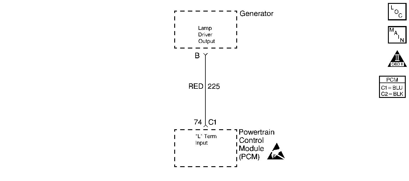
The generator communicates to the powertrain control module (PCM) over one line, the L or lamp circuit. The PCM uses the L circuit to monitor faults in the charging system. The generator L terminal indicates whether the PCM is allowing the generator to operate. The PCM can disable the generator under certain conditions in order to ease starting. Active indicates that the PCM is allowing generator operation, while inactive indicates that the PCM is not allowing generator operation.
Diagnostic Aids
| • | An Intermittent problem may be caused by a poor connection, rubbed through wire insulation, or a broken wire that inside the insulation. |
| • | Any circuitry, that is suspected as causing the intermittent complaint, should be thoroughly inspected for the following items: |
| - | Improper mating |
| - | Broken locks |
| - | Poor terminal to wiring connections |
| - | Physical damage to the wiring harness |
Test Description
The numbers below refer to the step numbers on the diagnostic table:
-
If the volts telltale lamp is not operating, either a short circuit or the IPC is malfunctioning. This determines whether the L circuit, generator, or IPC is malfunctioning.
-
If the charging system is not functioning, system voltage cannot be maintained above 12 V. Turning OFF all accessories assures that the system voltage is not being drawn down by an accessory that normally draws a large current.
-
If the lamp circuit is not shorted to ground, the volts telltale lamp will go OFF until the next key cycle when the test lamp is probed into terminal B. Be careful not to probe terminal C with the test lamp, this will turn off the volts telltale lamp whether or not the lamp circuit is shorted.
-
The PCM supplies a voltage to the generator. If voltage is available to the generator at this terminal, then the PCM and wiring are OK.
-
The replacement PCM must be programmed and the Crankshaft Position System Variation Learn procedure.
Step | Action | Values | Yes | No | ||||
|---|---|---|---|---|---|---|---|---|
1 | Did you perform the Powertrain On-Board Diagnostic (OBD) System Check? | -- | ||||||
2 | Turn ON the ignition, with the engine OFF. Is the volts telltale lamp on the IPC illuminated? | -- | ||||||
3 | Start and idle the engine. Did the volts telltale lamp on the IPC turn OFF? | -- | Go to Diagnostic Aids | |||||
Did the volts telltale lamp illuminated on the IPC? | -- | |||||||
Observe the scan tool, with all accessories OFF. Does the voltage read more than the specified value? | 12 V | |||||||
6 | With a test lamp connected to ground, probe the lamp signal circuit at the connector. Does the test lamp illuminate? | -- | ||||||
7 | Replace the instrument panel cluster (IPC). Refer to Instrument Cluster Replacement in Instrument Panel, Gauges and Console. Did you complete the replacement? | -- | -- | |||||
Does the test lamp illuminate? | -- | |||||||
9 | Repair the short to voltage in the lamp circuit. Refer to Wiring Repairs in Wiring Systems. Did you complete the repair? | -- | -- | |||||
10 | Repair the short to ground in the lamp circuit. Refer to Wiring Repairs in Wiring Systems. Did you complete the repair? | -- | -- | |||||
Does the voltage read more than the specified value? | 4.5 V | |||||||
12 | With the DMM still connected to a ground, probe the battery feed circuit to the generator. Does the DMM read the specified value? | B+ | ||||||
13 |
Did you find and correct the condition? | -- | ||||||
14 |
Did you find and correct the condition? | -- | -- | |||||
15 | Replace the generator. Refer to Generator Replacement in Engine Electrical. Did you complete the replacement? | -- | -- | |||||
|
Important:: The replacement PCM must be programmed. Replace the PCM. Refer to Powertrain Control Module Replacement/Programming . Did you completed the replacement? | -- | -- | ||||||
17 | Operate vehicle within the conditions under which the original symptom was noted. Does the system now operate properly? | -- | System OK |
