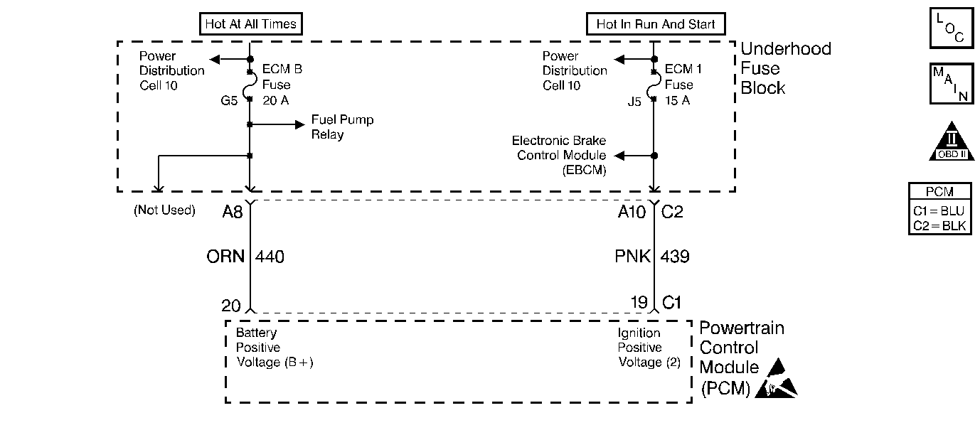
Circuit Description
The Powertrain Control Module (PCM) monitors the system voltage on the ignition positive voltage terminals to the PCM. A system voltage DTC sets whenever the voltage is above or below a specified calibrated value.
Conditions For Setting The DTC
The system voltage is more than 17 V.
Action Taken When the DTC Sets
| • | The PCM records the operating conditions at the time the diagnostic fails. The Failure Records buffers stores this information. |
| • | A history DTC is stored. |
Conditions for Clearing the DTC
| • | A History DTC clears after 40 consecutive warm up cycles without a fault. |
| • | Use a scan tool to clear the DTCs. |
Diagnostic Aids
| • | Charging the battery with a battery charger and starting the engine can cause a DTC to set. |
| • | Additional DTCs can set as the result of the PCM disabling the outputs. |
| • | If the DTC sets when you operate an accessory, check for a poor connection or an excessive current draw. |
An intermittent may be caused by any of the following conditions:
| • | A poor connection |
| • | Rubbed through wire insulation |
| • | A broken wire inside the insulation |
Thoroughly check any circuitry that is suspected of causing the intermittent complaint. Refer to Intermittents and Poor Connections Diagnosis in Wiring Systems.
If a repair is necessary, refer to Wiring Repairs or Connector Repairs in Wiring Systems.
Test Description
The numbers below refer to the step numbers on the Diagnostic Table.
-
The Powertrain OBD System Check prompts you to complete some of the basic checks and to store the freeze frame and failure records data on the scan tool if applicable. This creates an electronic copy of the data captured when this DTC set. The scan tool stores this data for later reference.
-
Program the replacement PCM and perform the Crankshaft Position System Variation Learn Procedure. Refer to the latest Techline procedures for PCM programming.
-
If no malfunctions are present at this point and no additional DTCs were set. Refer to Diagnostic Aids for additional checks and information.
Step | Action | Value(s) | Yes | No |
|---|---|---|---|---|
Did you perform the Powertrain On-Board Diagnostic (OBD) System Check? | -- | |||
2 |
Is the ignition voltage more than the specified value? | 1,400 RPM 17 V | ||
3 | Measure the battery voltage at the battery while running the engine at the specified value using a J 39200 DMM. Is the battery voltage less than the specified value? | 2,000 RPM 17 V | Go to Powertrain Control Module Controlled Generator Diagnosis | |
Is the action complete? | -- | -- | ||
5 |
Does the scan tool indicate that this diagnostic has ran and passed? | -- | ||
Check to see if any DTCs are set. Does the scan tool display any DTCs that you have not diagnosed? | -- | Go to the applicable DTC table | System OK |
