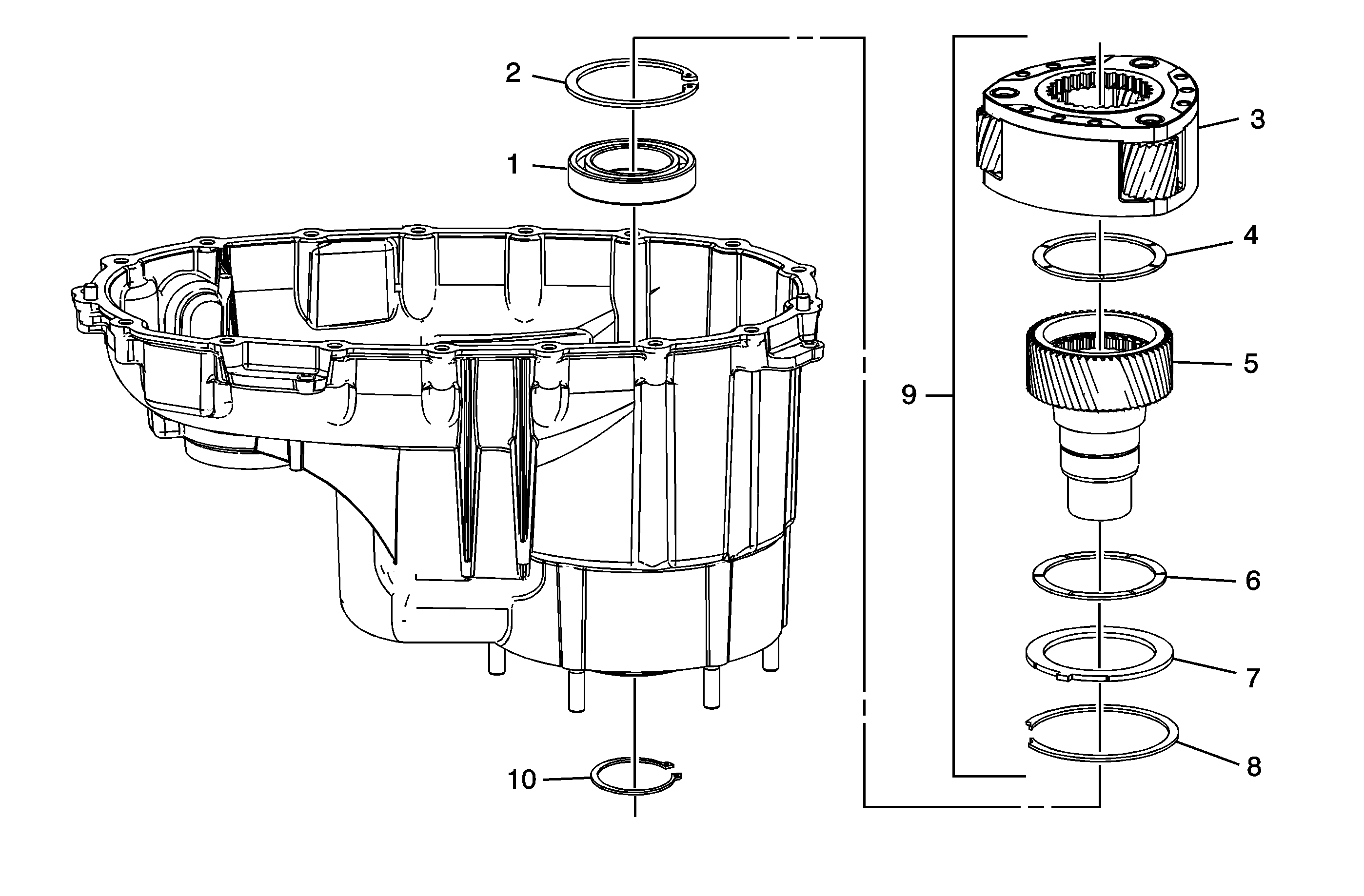
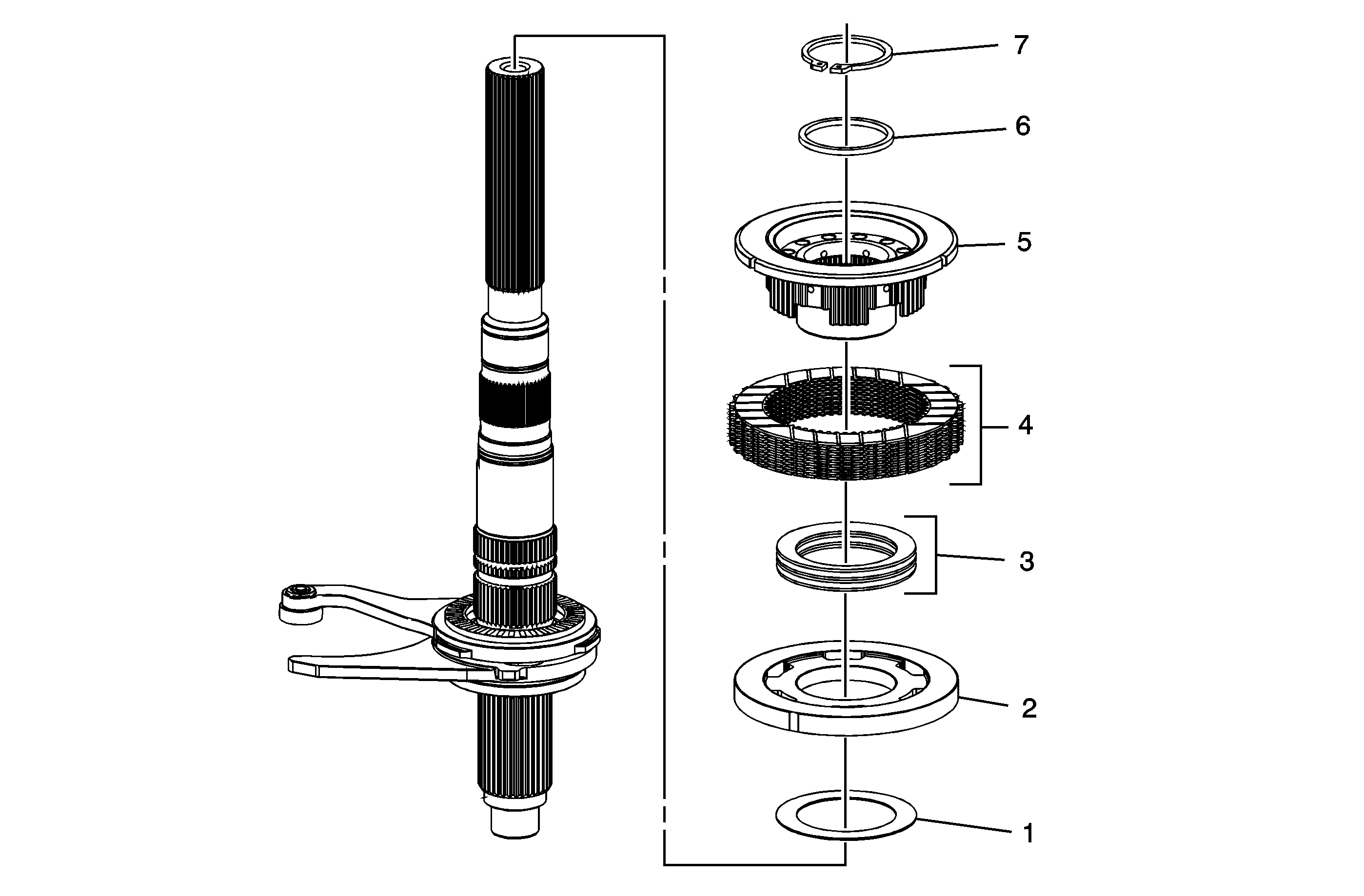
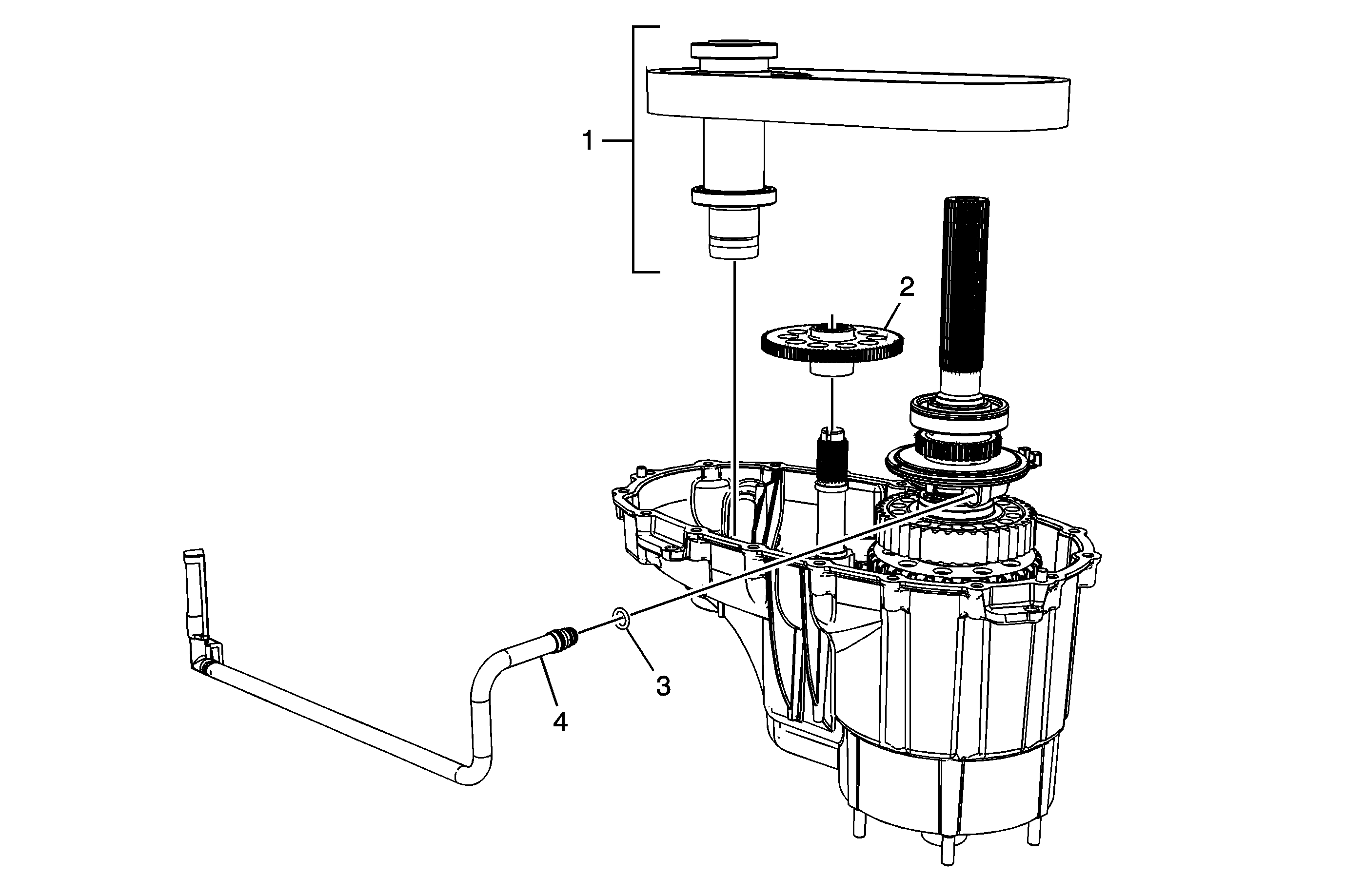
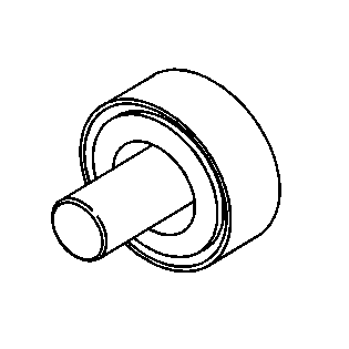
Input Shaft and Planetary Assembly Installation
Callout | Component Name |
|---|---|
1 | Transfer Case Input Shaft Bearing Assembly |
2 | Transfer Case Input Shaft Inner Retaining Ring |
3 | Transfer Case High/Low Planetary Carrier Assembly |
4 | Transfer Case Planetary Carrier Sun Gear Thrust Washer |
5 | Transfer Case Input Shaft |
6 | Transfer Case Planetary Carrier Sun Gear Thrust Washer |
7 | Transfer Case High/Low Locking Plate |
8 | Transfer Case High/Low Planetary Carrier Retaining Ring |
9 | Transfer Case Input Shaft/Planetary Assembly |
10 | Transfer Case Input Shaft Bearing Outer Retaining Ring |
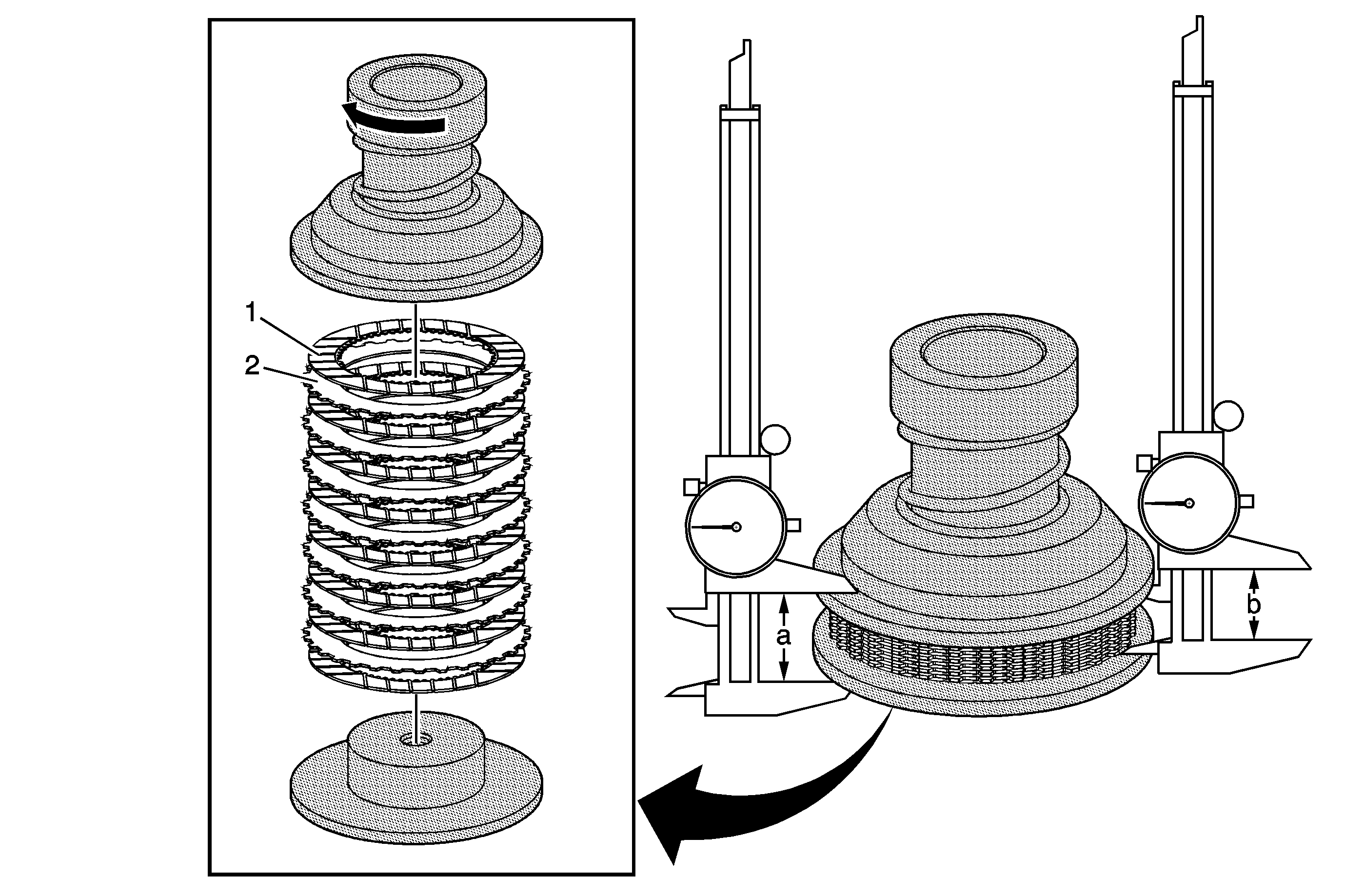
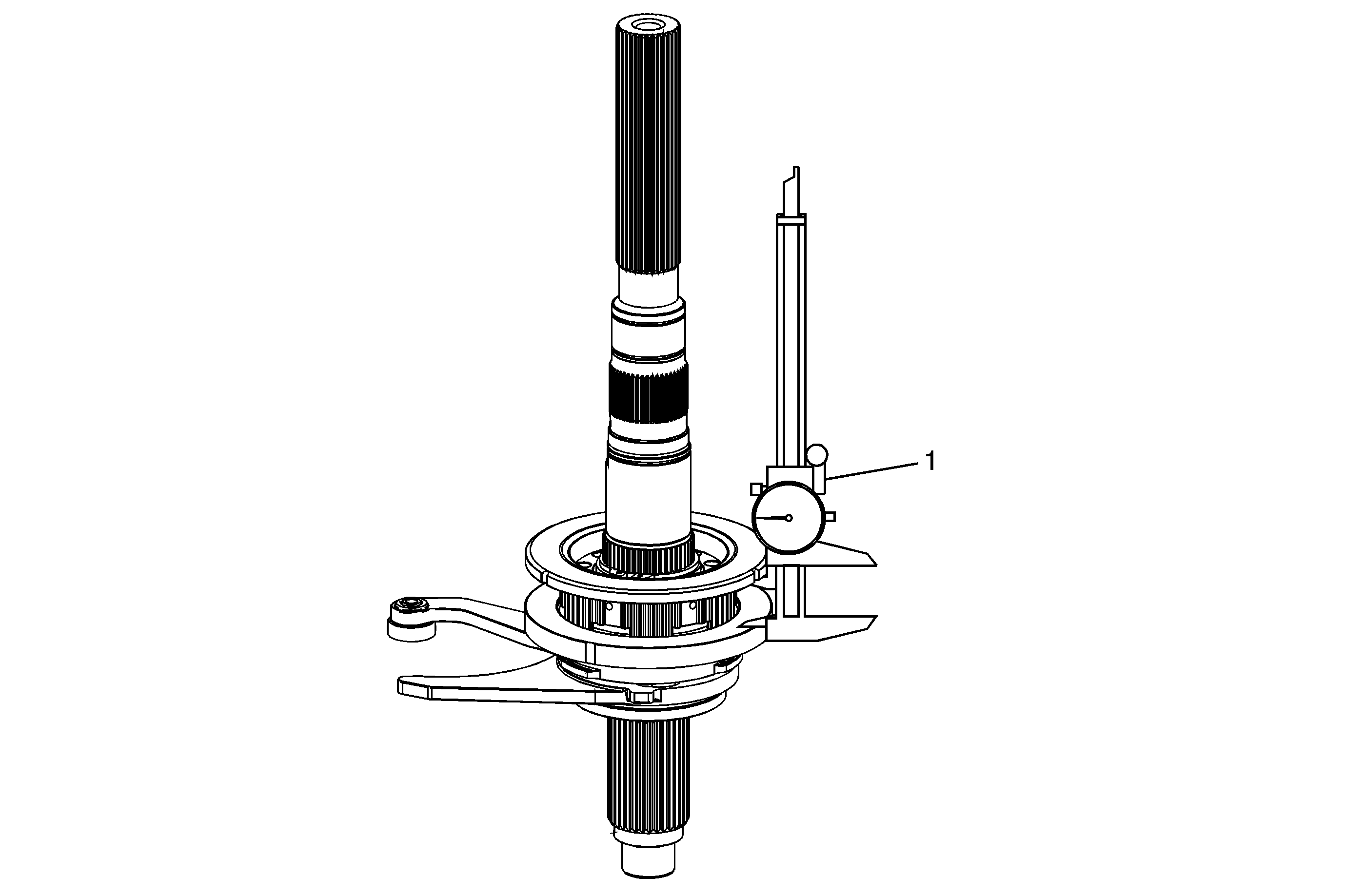
Measuring Clutch Pack Height
Callout | Component Name | ||||||
|---|---|---|---|---|---|---|---|
Preliminary Procedure
| |||||||
1 | Transfer Case Four Wheel Drive Clutch Pressure - Friction - Plates (Qty: 8) Tip Special ToolsDT-48213 Clutch Pack Height Gage | ||||||
2 | Transfer Case Four Wheel Drive Clutch Pressure - Steel - Plates (Qty: 7) Procedure 1 - Outside Measurement:
Procedure 2 - Inside Measurement:
Tip Special ToolsDT-48213 Clutch Pack Height Gage | ||||||
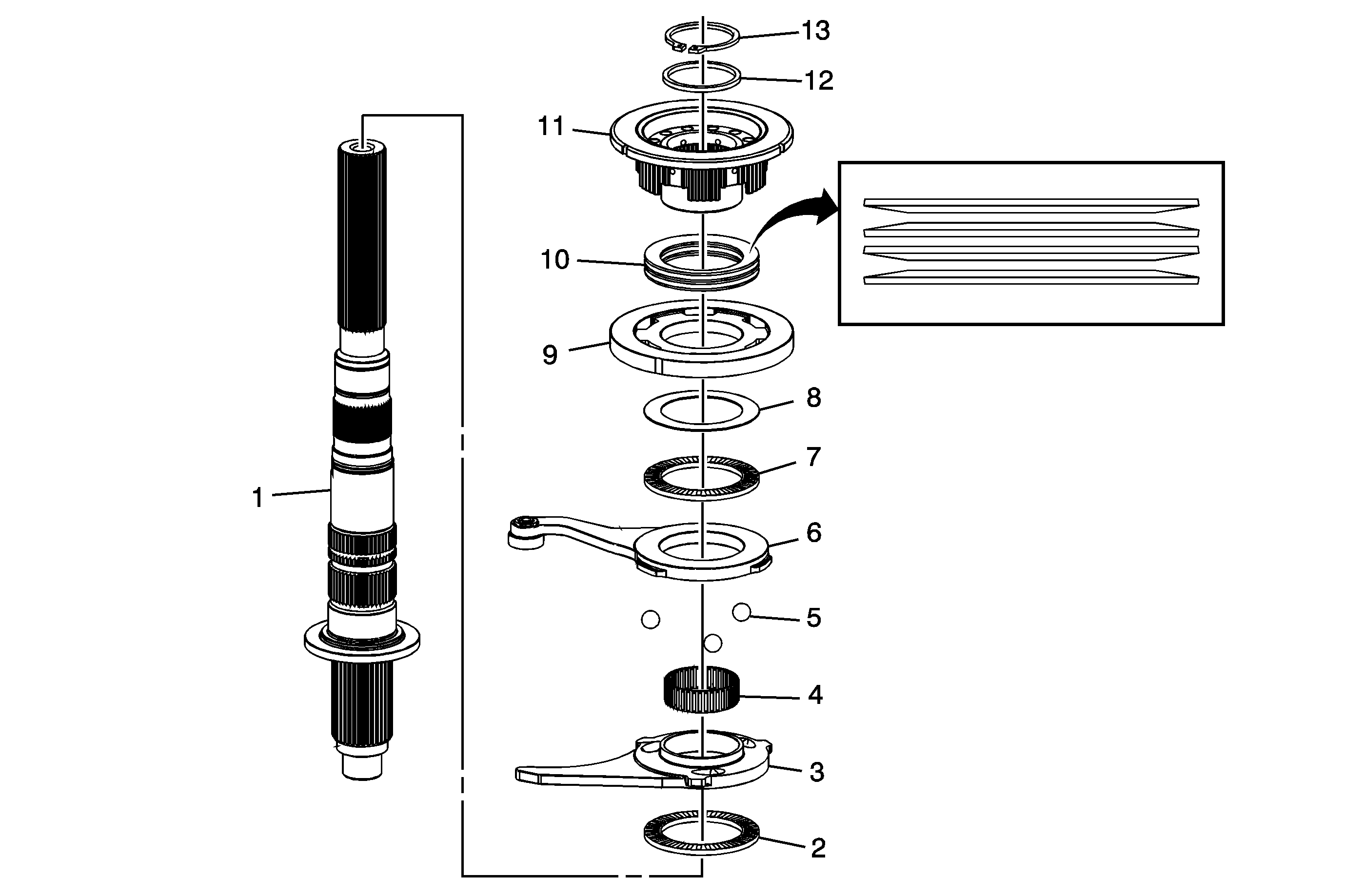
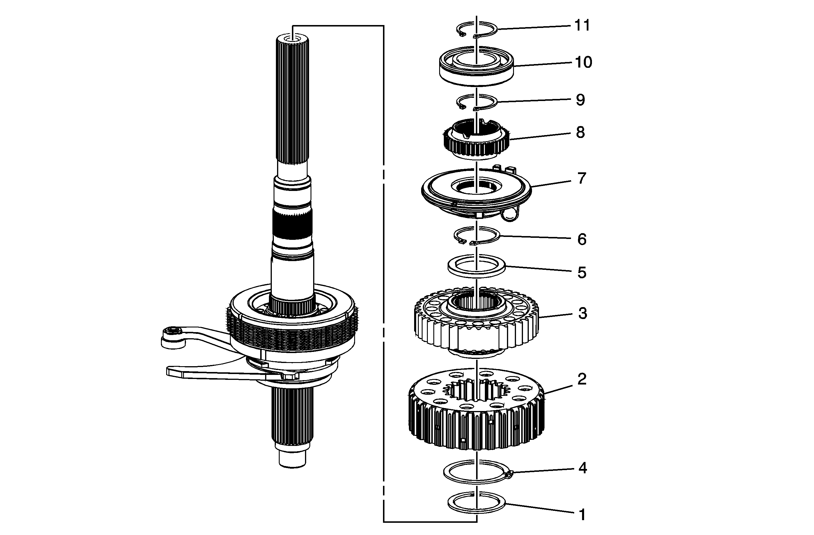
Clutch Assembly Installation
Callout | Component Name | ||||
|---|---|---|---|---|---|
1 | Transfer Case Rear Output Shaft | ||||
2 | Transfer Case Control Actuator Lever Thrust Bearing Assembly | ||||
3 | Transfer Case Control Lever | ||||
4 | Transfer Case Control Actuator Lever Bearing Assembly | ||||
5 | Transfer Case Control Actuator Lever Ball (Qty: 3) | ||||
6 | Transfer Case Control Actuator Lever Assembly | ||||
7 | Transfer Case Control Actuator Lever Thrust Bearing Assembly | ||||
8 | Transfer Case Control Actuator Lever Washer | ||||
9 | Transfer Case Four Wheel Drive Clutch Pressure - Apply - Plate Tip | ||||
10 | Transfer Case Four Wheel Drive Clutch Pressure Plate Spring (Qty: 4) | ||||
11 | Transfer Case Four Wheel Drive Clutch Hub | ||||
12 | Transfer Case Four Wheel Drive Clutch Shim Tip
| ||||
13 | Transfer Case Two/Four Wheel Drive Clutch Retaining Ring Tip |
Measuring/Adjusting Clutch Assembly Height
Callout | Component Name | ||||
|---|---|---|---|---|---|
1 | Clutch Assembly Procedure:
Tip
|
Clutch Pressure Plate Installation
Callout | Component Name |
|---|---|
1 | Transfer Case Control Actuator Lever Washer |
2 | Transfer Case Four Wheel Drive Clutch Pressure - Apply - Plate |
3 | Transfer Case Four Wheel Drive Clutch Pressure Plate Spring (Qty: 4) |
4 | Transfer Case Four Wheel Drive Clutch Pressure Plates |
5 | Transfer Case Four Wheel Drive Clutch Hub |
6 | Transfer Case Four Wheel Drive Clutch Shim |
7 | Transfer Case Two/Four Wheel Drive Clutch Retaining Ring Tip |
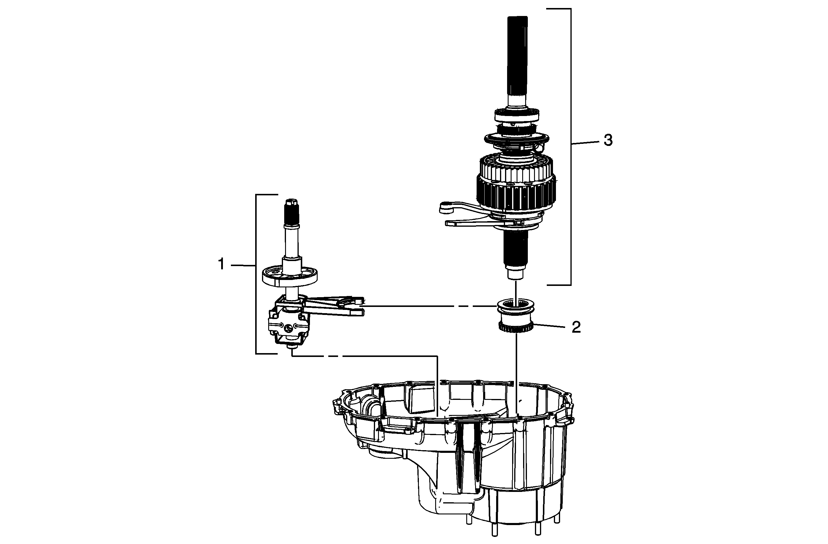
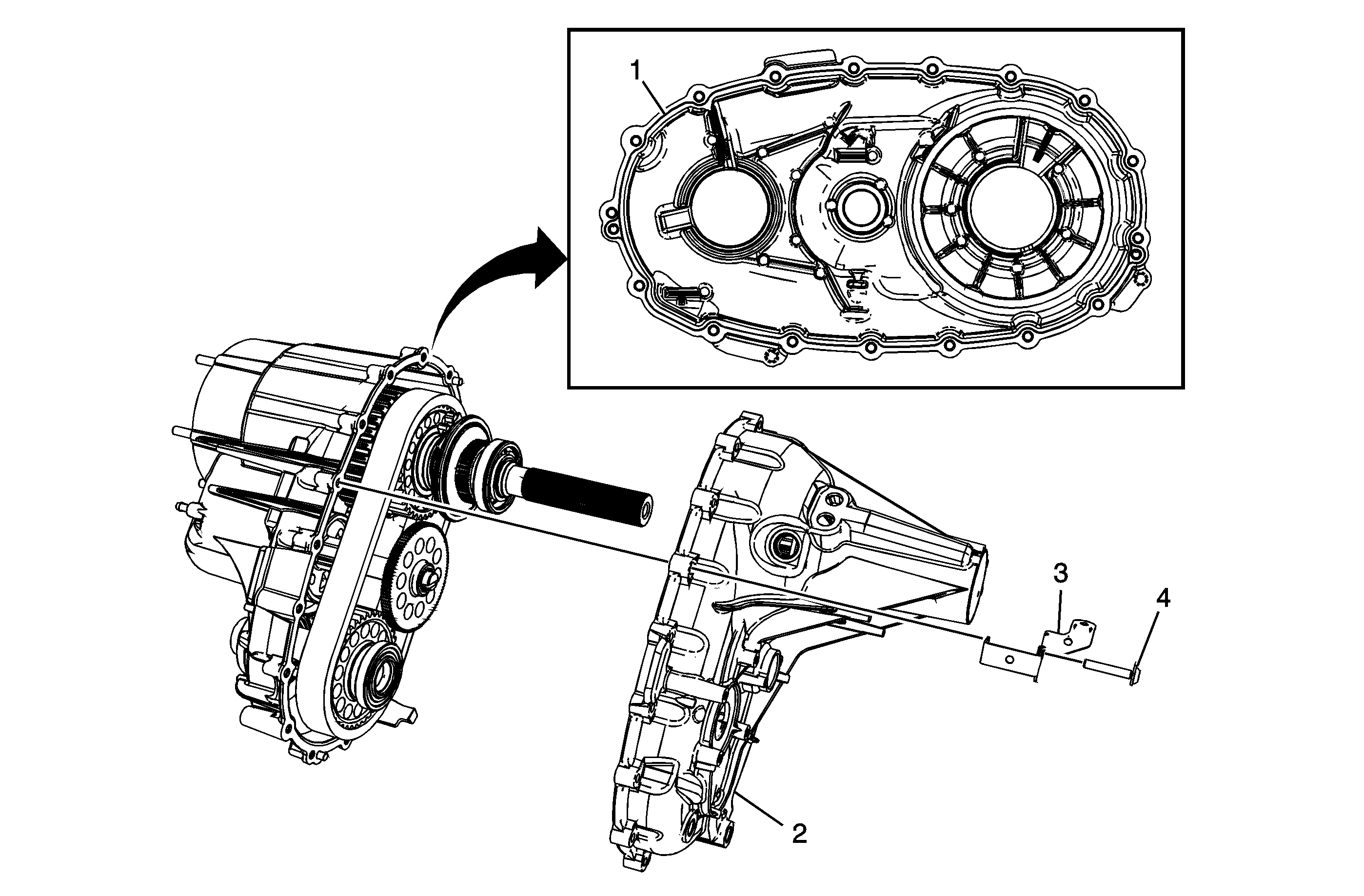
Rear Output Shaft Assembly
Callout | Component Name | ||||
|---|---|---|---|---|---|
1 | Transfer Case Front Output Shaft Drive Sprocket Spacer - Front | ||||
2 | Transfer Case Four Wheel Drive Clutch Housing | ||||
3 | Transfer Case Front Output Shaft Drive Sprocket | ||||
4 | Transfer Case Four Wheel Drive Clutch Housing Retaining Ring | ||||
5 | Transfer Case Front Output Shaft Drive Sprocket Spacer - Rear | ||||
6 | Transfer Case Front Output Shaft Drive Sprocket Retaining Ring | ||||
7 | Transfer Case Oil Pump Assembly | ||||
8 | Transfer Case Rear Output Shaft Speed Reluctor Wheel | ||||
9 | Transfer Case Rear Output Shaft Rear Bearing Retaining Ring | ||||
10 | Transfer Case Rear Output Shaft Rear Bearing Assembly Tip
| ||||
11 | Transfer Case Rear Output Shaft Rear Bearing Retaining Ring |
Shift Fork Assembly, and Rear Output Shaft Assembly Installation
Callout | Component Name |
|---|---|
Preliminary ProcedureLoad all 3 components simultaneously. | |
1 | Transfer Case High/Low Shift Fork Assembly |
2 | Transfer Case High/Low Clutch |
3 | Transfer Case Rear Output Shaft Assembly |
Front Output Shaft Assembly, Drive Chain, Actuator Shaft Gear, and Oil Pump Suction Pipe Installation
Callout | Component Name | ||||||
|---|---|---|---|---|---|---|---|
1 | Transfer Case Front Output Shaft Assembly, Transfer Case Front Output Shaft Drive Chain Assembly Tip
| ||||||
2 | Transfer Case Actuator Shaft Gear | ||||||
3 | Transfer Case Oil Pump Suction Pipe Seal Tip
| ||||||
4 | Transfer Case Oil Pump Suction Pipe |
Transfer Case Rear Case Half Installation
Callout | Component Name | ||||||
|---|---|---|---|---|---|---|---|
1 | Sealer GM P/N 12345739 (Canadian P/N 10953541), or equivalent Notice: Apply the proper amount of sealant to the flange when assembling the transfer case. Excessive amounts of sealant can plug the oil pump screen, resulting in internal component failure. Tip
| ||||||
2 | Transfer Case Rear Case Half Tip
| ||||||
3 | Transfer Case Bracket | ||||||
4 | Transfer Case Bolts (Qty: 17) Notice: Refer to Fastener Notice in the Preface section. Tip Tighten |
Rear Output Shaft Seal and Bushing Installation
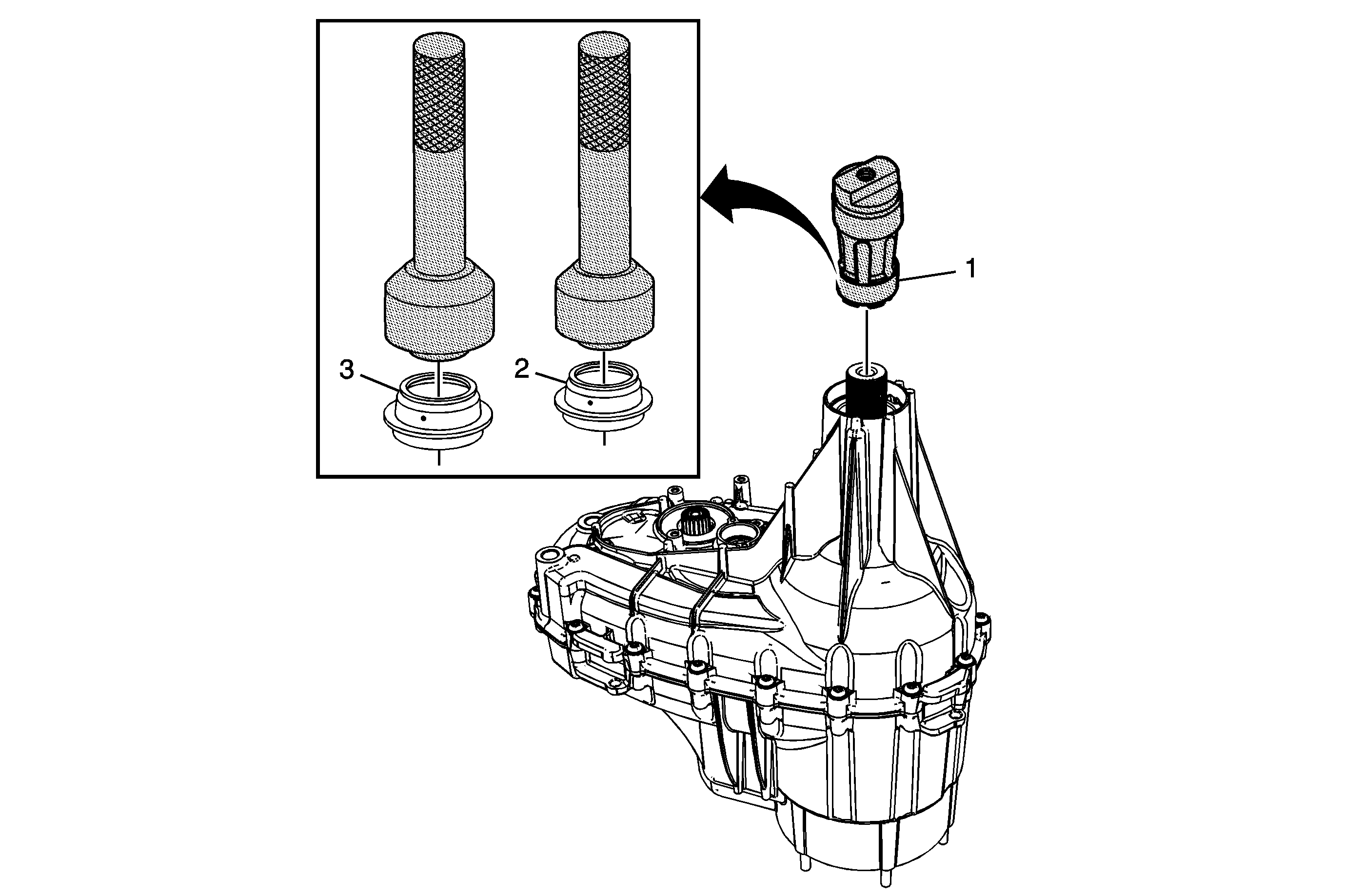
Callout | Component Name | ||||||||||||||
|---|---|---|---|---|---|---|---|---|---|---|---|---|---|---|---|
Preliminary ProcedureThe following procedure is for the light duty application, for the heavy duty and super heavy duty applications. Refer to Rear Output Shaft Bushing Replacement. | |||||||||||||||
1 | Transfer Case Rear Output Shaft Bushing (Light Duty) Tip
Special ToolsJ 45380 Transfer Case Rear Bushing Remover and Installer | ||||||||||||||
2 | Transfer Case Rear Output Shaft Seal (Light Duty) Tip Special Tools
| ||||||||||||||
3 | Transfer Case Rear Output Shaft Seal (Heavy Duty) Tip Special Tools
| ||||||||||||||
Access Hole Plugs, Fill and Drain Plug, Vent, 2/4 Wheel Drive Actuator, Actuator Shaft Position Sensor, and Vehicle Speed Sensor Installation
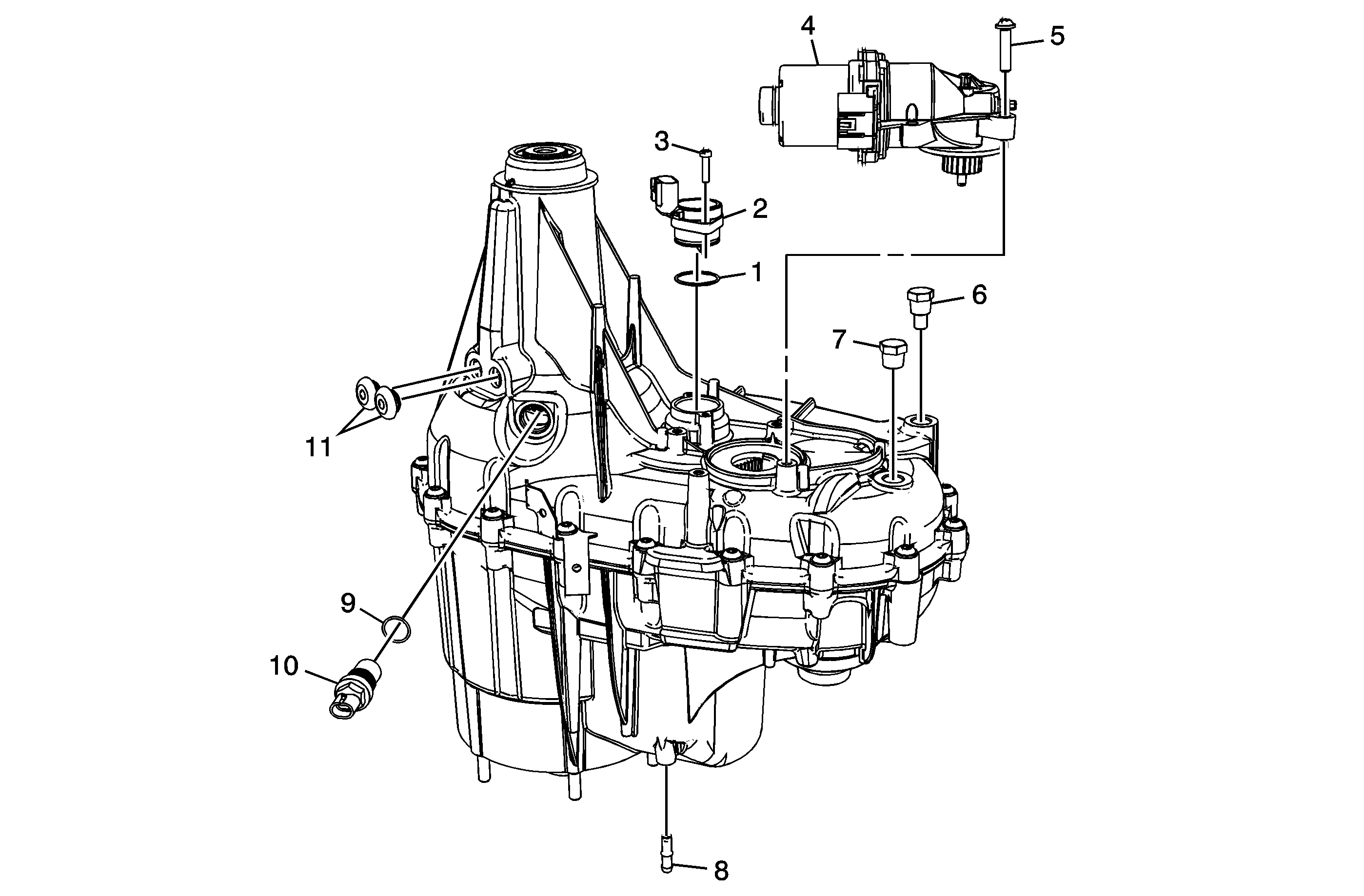
Callout | Component Name |
|---|---|
1 | Transfer Case Actuator Shaft Position Sensor O-Ring Seal Tip |
2 | Transfer Case Actuator Shaft Position Sensor Assembly |
3 | Transfer Case Actuator Shaft Position Sensor Bolt/Screw Tighten |
4 | Transfer Case Two/Four Wheel Drive Actuator Assembly |
5 | Transfer Case Two/Four Wheel Drive Actuator Bolt/Screw Tighten |
6 | Transfer Case Oil Drain Plug Notice: Refer to Component Fastener Tightening Notice in the Preface section. Tip Tighten |
7 | Transfer Case Oil Fill Plug Tip Tighten |
8 | Transfer Case Vent Tip |
9 | Vehicle Speed Sensor O-Ring Seal Tip |
10 | Vehicle Speed Sensor Assembly Tighten |
11 | Transfer Case Access Hole Plugs (Qty: 2) |
Input Shaft Seal and Front Output Shaft Seal Installation
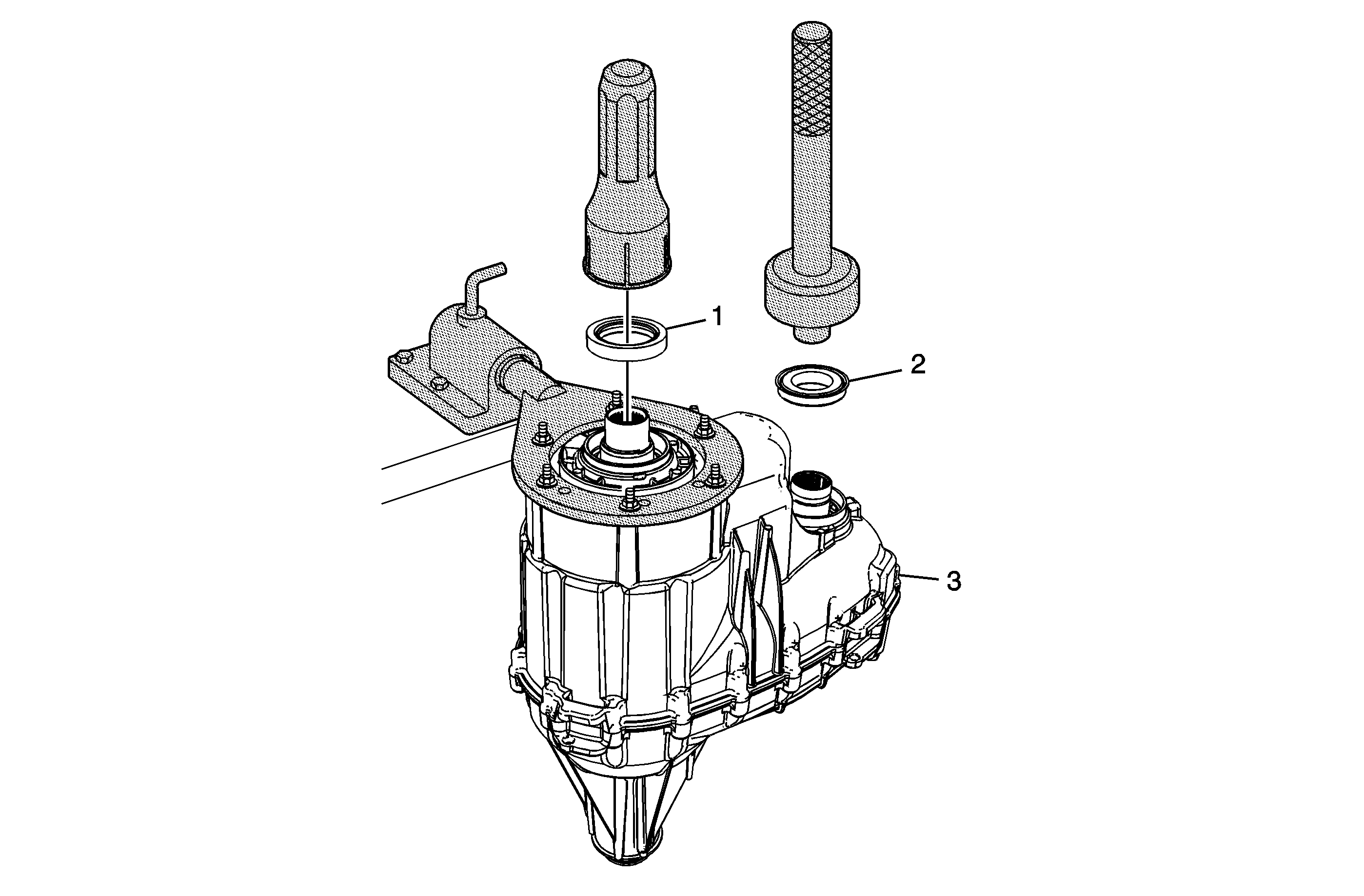
Callout | Component Name | ||||
|---|---|---|---|---|---|
1 | Transfer Case Input Shaft Seal Tip Special ToolsJ 42738 Seal Installer | ||||
2 | Transfer Case Front Output Shaft Seal Special Tools
| ||||
3 | Transfer Case Assembly Tip |
