
| Subject: | Loss Of High Speed GMLAN Communications, Intermittent No Crank, IPC Gauge Fluctuation, Intermittent Door Lock Cycling, Transmission May Not Shift, DTCs U0073, U0100, U0101, U0102, U0121, U0140 (Repair Backed Out Terminal In Transmission Harness Connector) |
| Models: | 2007-2008 Cadillac Escalade Models, XLR |
| 2007-2008 Chevrolet Corvette, Silverado, Suburban, Tahoe |
| 2007-2008 GMC Sierra, Yukon Models |
| with 6 Speed 6L80 (RPO MYC) or 6L90 (RPO MYD) Automatic Transmission |
Condition
Some customers may comment of any of the following conditions:
| • | The transmission may not shift. |
| • | The door locks may cycle by themselves. |
| • | The engine may not crank intermittently. |
| • | The Instrument Panel Cluster (IPC) gauges may fluctuate. |
Technicians may find the following High Speed GMLAN Communications Diagnostic Trouble Codes (DTCs) shown as a current code or stored in history:
| • | U0073: Control Module Communications Bus OFF |
| • | U0100: Lost Communication With ECM/PCM |
| • | U0101: Lost Communication With TCM |
| • | U0102: Lost Communication With Transfer Case Control Module |
| • | U0121: Lost Communication With Anti-Lock Brake System (ABS) Control Module |
| • | U0140: Lost Communication With Body Control Module |
Cause
These conditions may be caused by a terminal for the High Speed GMLAN Serial Data Bus that has backed out of the 16-way electrical connector to the automatic transmission.
Correction
Do This
| Don't Do This
|
Repair or replace backed out transmission connector terminals as necessary. Ensure that the TPA is fully seated (TPA centered in check window) prior to reinstalling the connector.
| Do NOT replace BCM, ECM, EBCM or wiring harness before checking terminals in transmission connector.
|
Technicians are to inspect and repair the 16-way electrical connector at the transmission using the following procedure:
- Disconnect the negative battery cable. Refer to the Battery Cable Disconnection and Connection procedure in SI.
- Raise and suitably support the vehicle. Refer to the Lifting and Jacking procedure in SI.
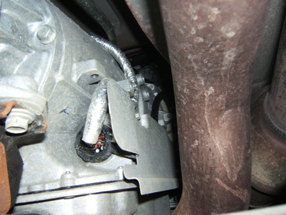
- Locate the 16-way electrical connector on the right side of the automatic transmission. Refer to the illustration above, which shows the location of the 16-way connector.
- Inspect the connector for any backed out terminals. If a backed out terminal is found, identify the terminal that has backed out on the repair order. Look at the connector in order to identify the number of the cavity with the backed out terminal.
Look up the connector end view in SI to determine the corresponding circuit number and to verify the cavity number with the backed out terminal.
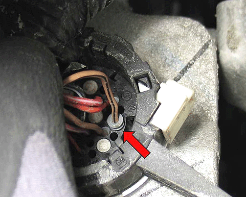
- The illustration above shows what to look for - a backed out female terminal.
- Remove the transmission connector and repair or replace the terminal(s) as necessary. If the female terminal must be replaced, it is part number 22124472200. It is located in Yazaki tray number 12 in the J-38125 Terminal Repair Kit. Refer to the
repair procedures in the Wiring Systems And Power Management section of SI for more information.
- Inspect the terminals in the transmission itself (male half of the connection). Are any of the male terminals bent? If so, refer to the connector end view document in SI to identify the bent terminal. Repair the terminals as necessary.
- Prior to reinstalling the transmission connector, perform the following steps to ensure that the Terminal Position Assurance (TPA) lock is fully seated.
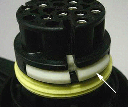
| 8.1. | Locate the TPA lock in the reassembled transmission connector. Refer to the arrow in the illustration above, which points to a TPA lock. This one is in an unseated position. Seat the TPA using a small screwdriver in
the slot. Use the following SI document path to access the Kostal Connector (transmission harness connector) repair information in SI. |
| - | Select Power and Signal Distribution |
| - | Select Wiring Systems and Power Management |
| - | Select Diagnostic Information and Procedures |
| - | Select Kostal Connectors (Transmission) |
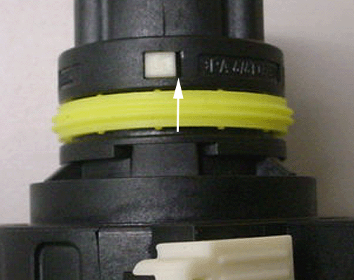
| 8.2. | Check to see if the TPA is fully seated. If the TPA is centered in the check window, then the TPA is fully seated. If the TPA is off-center in the check window, as shown in the illustration above, then the TPA is only partially
seated. Note the large gap at the arrow. If the TPA is only partially seated, it will be necessary to reseat the TPA lock and recheck to ensure that it is fully seated. |
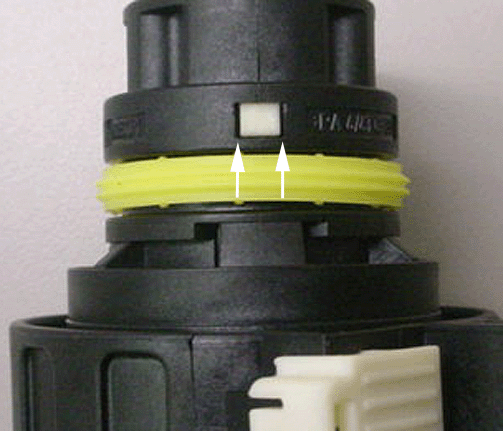
| 8.3. | The TPA lock should be centered in the window. Refer to the illustration above, which shows the TPA lock centered in the check window. The gaps shown by the arrows are even on both sides. |
- Install the transmission connector. Note on the repair order which terminal number or numbers were repaired or replaced and if a male terminal was bent. Indicate the number of the terminal that was bent.
- Lower the vehicle.
- Reconnect the negative battery cable. Refer to the Battery Cable Disconnection and Connection procedure in SI.
- Clear the DTCs and verify proper operation of the vehicle.
- If no terminal or connector concerns are found, refer to the Diagnostic System Check procedure in SI to begin your diagnosis of these customer concerns.
Parts Information
If the female terminal must be replaced, the terminal part number is 22124472200. It is located in Yazaki tray number 12 in the J-38125 Terminal Repair Kit.
Warranty Information
For vehicles repaired under warranty, use:
Labor Operation
| Description
| Labor Time
|
N6629
| Wiring And/Or Connector-Transmission - Repair Or Replace
| Use Published Labor Operation Time
|
Please note in the technicians comments field on the repair order which terminal number or numbers were repaired or replaced. Also, if a male terminal is bent (transmission side of connector), then indicate the bent terminal number on the repair order.


