Special Tools
| • | J 21366 Converter Holding Strap |
| • | J 44257 Connector Removal Tool |
Removal Procedure
Important: If replacing a failed transmission, the "FastLearn" (adapt) procedure must be performed. This can be done in one step using a scan tool. If this procedure is not done, the transmission control module's (TCM's) adaptive values will still be at the settings that it learned for the old transmission, and will be in slow adaptive mode. Under these conditions, it would take an unacceptably long time for the adaptive values to converge to levels suitable for the new transmission.
- Remove the transmission fluid level indicator.
- Remove the starter motor. Refer to Starter Motor Replacement.
- Rotate the engine clockwise, using the crankshaft bolt in order to access the torque converter bolts through the starter opening. Have an assistant rotate the engine while aligning the bolts.
- Remove the torque converter bolts.
- Completely raise the vehicle.
- Drain the transmission fluid.
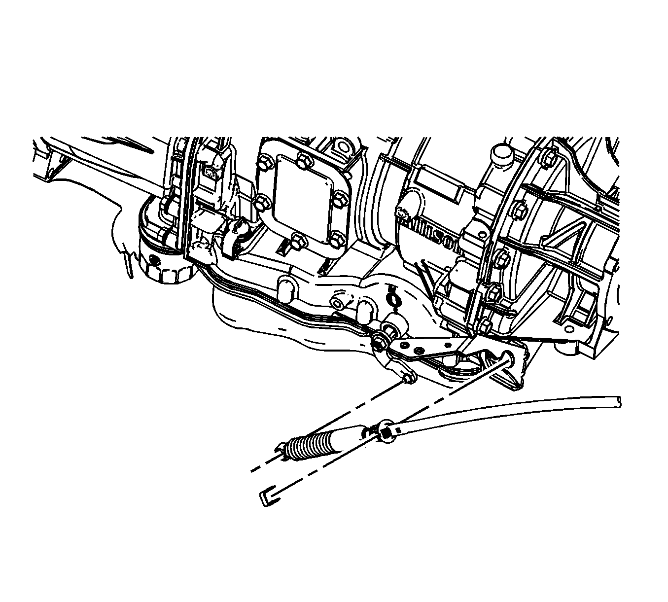
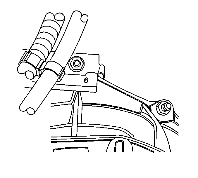
- Remove the range selector cable heat shield bolts.
- Remove the range selector cable heat shield.
- Remove the range selector cable end from the transmission range selector lever stud.
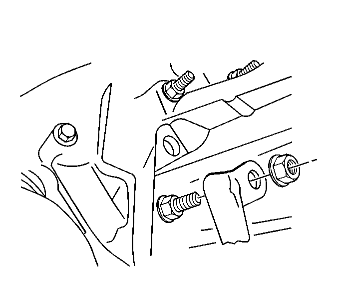
- Remove the shift cable bracket bolts and bracket from the transmission.
- Position the bracket with the cable attached out of the way.
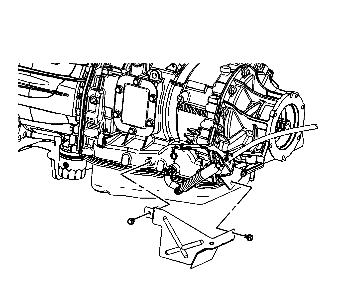
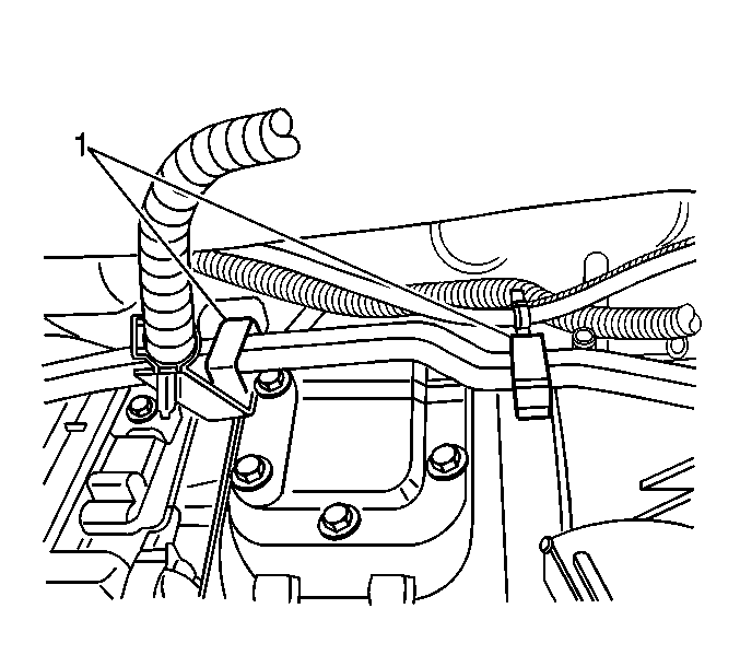
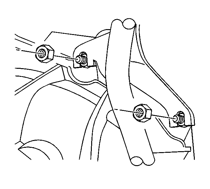
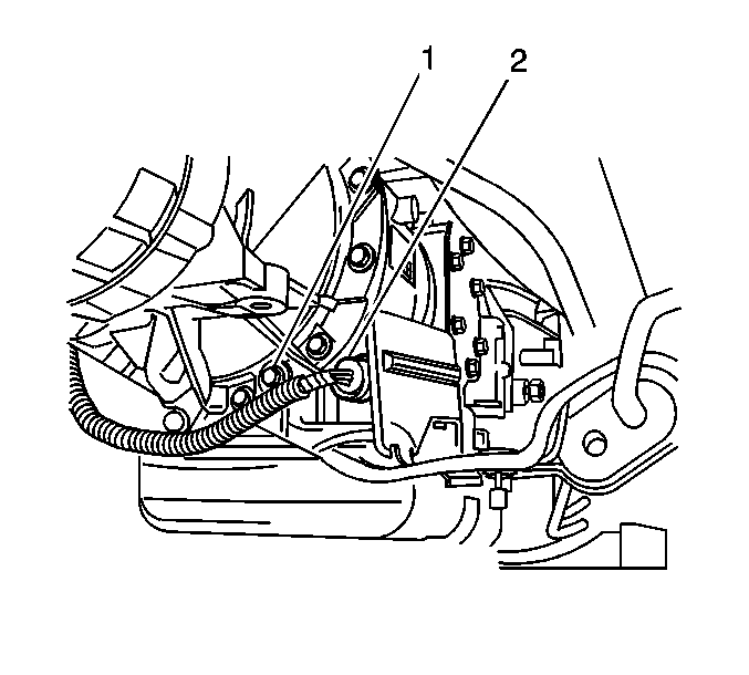
- Remove the fuel line retainer (1) bolts on the left side of the transmission.
- Remove the fuel line bracket nut from the converter housing stud.
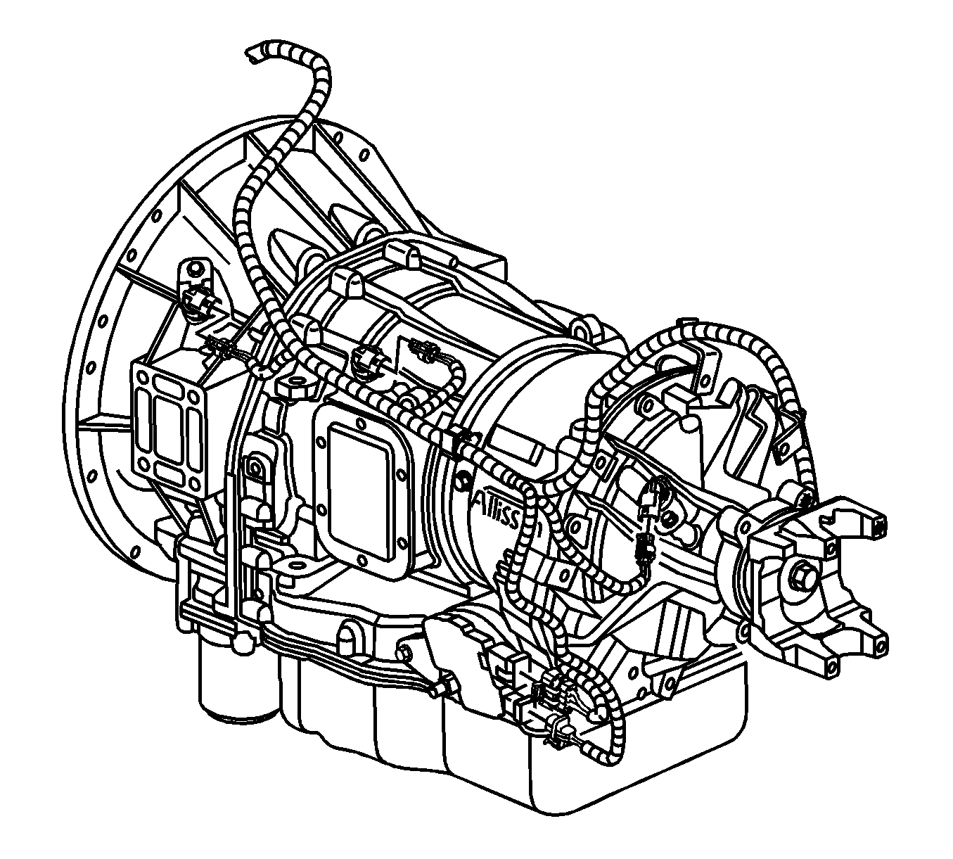
- Disconnect the electrical connectors on the transmission and transfer case, if equipped.
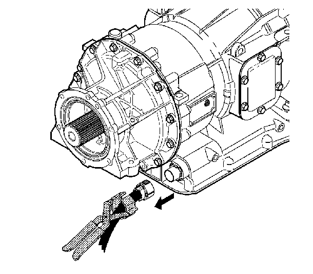
- Disconnect the transmission main electrical connector. J 44257 may be used, but is not required.
- Remove the transmission heat shield. Refer to Transmission Heat Shield Replacement.
- Remove the exhaust hanger bolts and reposition the hanger.
- Support the transmission with a transmission jack.
- Two wheel drive vehicles remove the propeller shaft. Refer to One-Piece Propeller Shaft Replacement or Two-Piece Propeller Shaft Replacement.
- Two wheel drive vehicles, remove the transmission support. Refer to Transmission Support Crossmember Replacement.
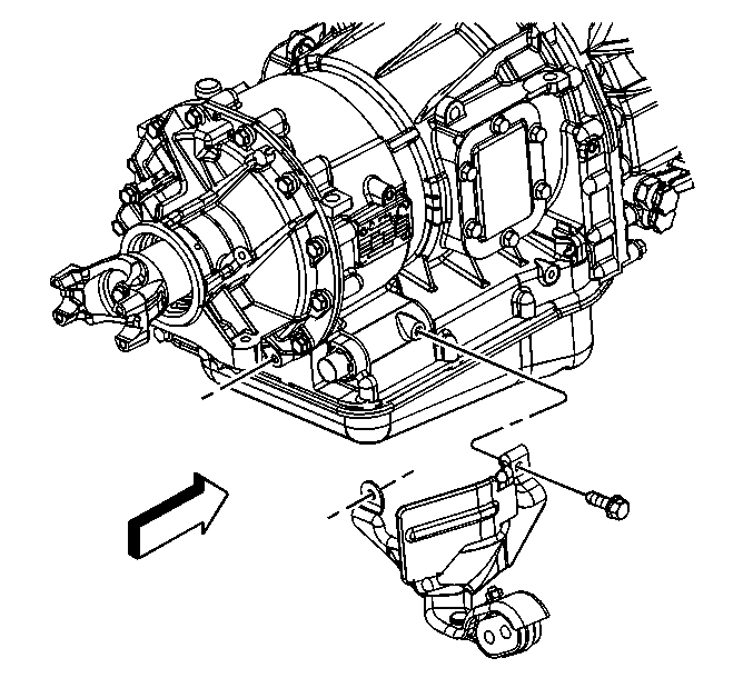
- Two wheel drive vehicles, remove the transmission mount from the transmission. Refer to Transmission Mount Replacement.
- Four wheel drive vehicles, remove the transfer case. Refer to the appropriate procedure:
- Reposition any wiring harness branches out of the way.
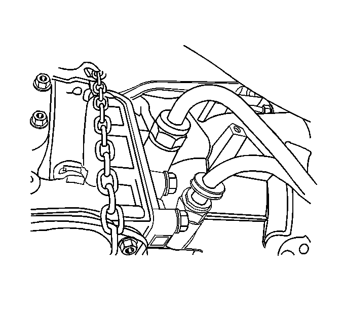
- Secure a safety chain around the transmission. Use care not to overlap any wiring, fuel lines, or other related components.
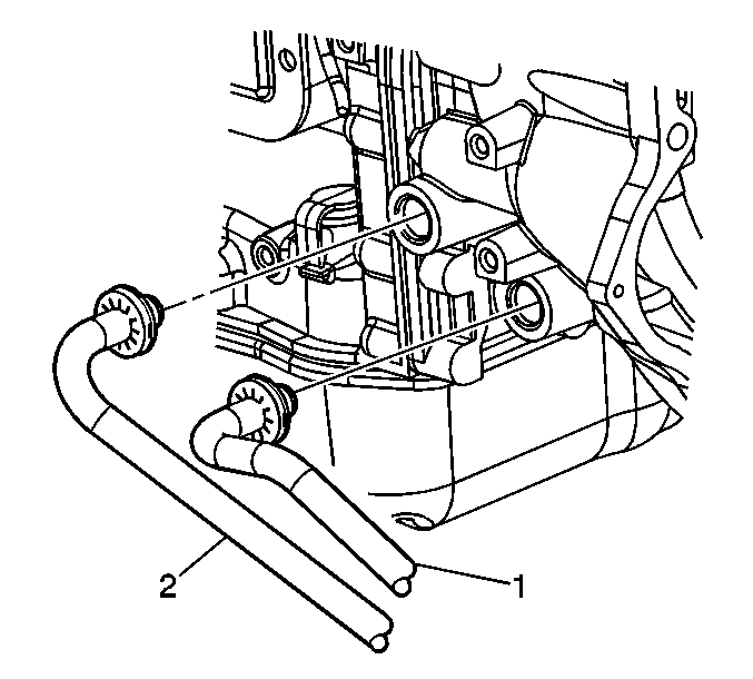
- Disconnect the transmission oil cooler lines (1, 2) from the transmission. Refer to Transmission Fluid Cooler Hose/Pipe Quick-Connect Fitting Disconnection and Connection.
- Plug the transmission oil cooler line fittings in the transmission case, if necessary.
- If the vehicle is equipped with a power take off (PTO) unit , disconnect and/or remove any necessary components to facilitate transmission removal.
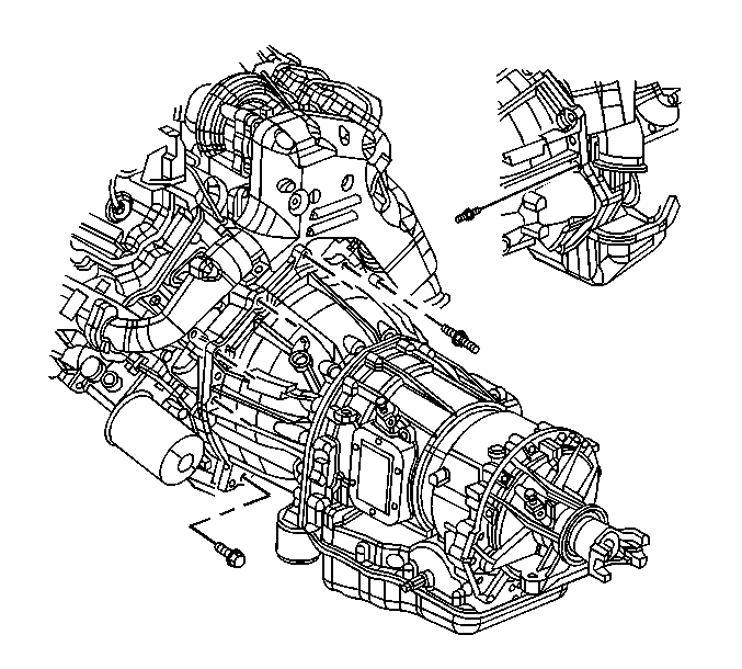
- Remove the transmission fill tube nuts from the converter housing studs.
- Remove the wire harness/vent tube bracket nut from the converter housing stud and reposition the bracket.
- Remove the remaining converter housing bolts and studs.
- Separate the transmission from the engine.
- Install J 21366 to the converter housing in order to keep the torque converter from sliding off of the turbine shaft.
- Carefully lower the transmission from the vehicle while simultaneously removing the fill tube.
- Remove the J 21366 .
Important: Rotate the engine clockwise ONLY, rotating the engine counterclockwise may loosen the crankshaft balancer bolt.

| • | If equipped with a NQG, refer to Transfer Case Assembly Replacement. |
| • | If equipped with a NQF, refer to Transfer Case Assembly Replacement. |
Installation Procedure
- Install J 21366 to the converter housing in order to keep the torque converter from sliding off of the turbine shaft.
- Raise the transmission into place while simultaneously installing the transmission fill tube.
- Remove the J 21366
- Align the transmission with the engine using the alignment dowels located at the rear of the engine.
- Install the converter housing bolts and studs.
- Install the wire harness/vent tube bracket and nut to the converter housing stud.
- Install the transmission fill tube and nuts to the converter housing studs.
- If the vehicle is equipped with a PTO unit, connect and/or install the components at this time.
- Remove the safety chain from around the transmission.
- Four wheel drive vehicles install the transfer case, transmission support and propeller shafts. Refer to the appropriate procedure:
- Two wheel drive vehicles, install the transmission mount to the transmission. Refer to Transmission Mount Replacement.
- Two wheel drive vehicles, install the transmission support. Refer to Transmission Support Crossmember Replacement.
- Two wheel drive vehicles, install the propeller shaft. Refer to One-Piece Propeller Shaft Replacement or Two-Piece Propeller Shaft Replacement.
- Position the exhaust hanger and install the bolts.
- Install the transmission heat shield. Refer to Transmission Heat Shield Replacement.
- Position the wiring harness branches.
- Connect the transmission main electrical connector (2).
- Connect the electrical connectors on the transmission and transfer case, if equipped.
- Install the fuel line bracket and nut to the transmission converter housing stud.
- Install the fuel line retainer (1) and bolts to the left side of the transmission.
- Install the shift cable bracket and bolts to the transmission.
- Install the range selector cable end to the transmission range selector lever stud.
- Install the range selector cable heat shield.
- Install the range selector cable heat shield bolts.
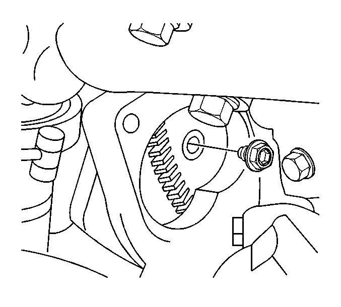
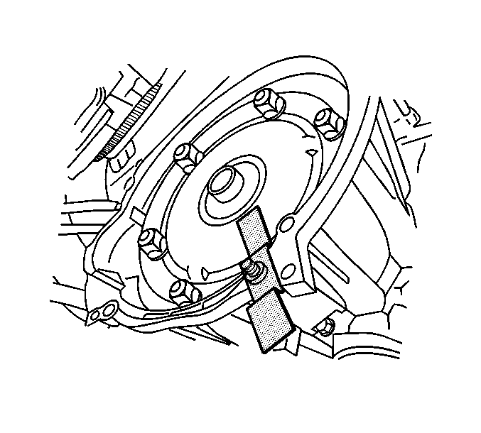
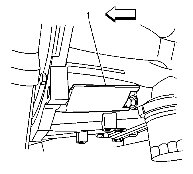
- Remove the access hole cover (1) on the converter housing in order to rotate the converter and align the first torque converter bolt.
- If reusing the torque converter bolts, clean the bolt threads and apply LOCTITE 242 GM P/N 12345382 (Canadian P/N 10953489), or equivalent to the threads prior to installation.
- Install the torque converter bolts.
- Install the converter housing access hole cover.
- Install the starter motor. Refer to Starter Motor Replacement.
- Remove the plugs from the transmission oil cooler line fittings in the transmission case, if necessary.
- Flush the transmission oil cooler and lines, if necessary. Refer to Transmission Fluid Cooler Flushing and Flow Test.
- Connect the transmission oil cooler lines (1, 2) to the transmission. Refer to Transmission Fluid Cooler Hose/Pipe Quick-Connect Fitting Disconnection and Connection.
- Lower the vehicle.
- Install the cooling fan and shroud. Refer to Cooling Fan and Shroud Replacement.
- Connect both negative battery cables. Refer to Battery Negative Cable Disconnection and Connection.
- Fill the transmission with new transmission fluid.
- Install the transmission fluid level indicator.
- If a replacement transmission was installed, perform the "FastLearn" procedure using a scan tool. Refer to FastLearn Procedure.
Important: Do not install the transmission by drawing it to the engine using the studs and bolts.
Notice: Refer to Fastener Notice in the Preface section.
Important: Ensure that the torque converter can be rotated before tightening the bolts and studs.
Tighten
Tighten the bolts/studs to 50 N·m (37 lb ft).
Tighten
Tighten the nut to 18 N·m (13 lb ft).
Tighten
Tighten the nuts to 18 N·m (13 lb ft).
| • | If equipped with a NQG, refer to Transfer Case Assembly Replacement. |
| • | If equipped with a NQF, refer to Transfer Case Assembly Replacement. |
Tighten
Tighten the bolts to 12 N·m (106 lb in).
Tighten
Tighten the nut to 18 N·m (13 lb ft).
Tighten
Tighten the bolts to 2.5 N·m (22 lb in).
Tighten
Tighten the bolts to 25 N·m (18 lb ft).
Important: Install bolts by hand then mechanically tighten the front bolt first and the rear bolt last. Failure to tighten the bolts in the specified order will result in misalignment of the heat shield.
Tighten
| • | Tighten the front bolt to 25 N·m (18 lb ft). |
| • | Tighten the rear bolt to 25 N·m (18 lb ft). |
Tighten
Tighten the bolts to 60 N·m (44 lb ft).
