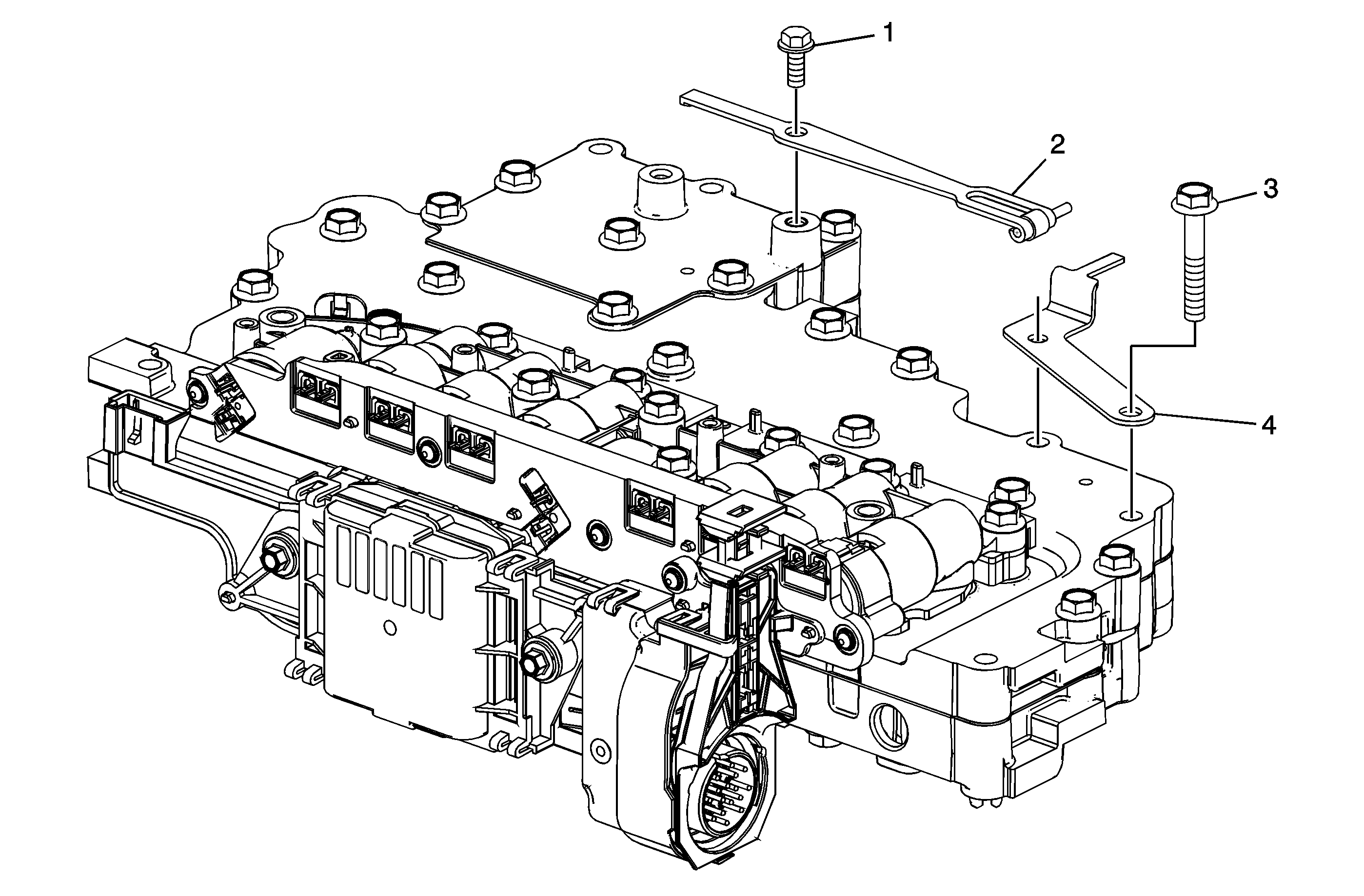
Manual Shaft Detent Assembly Removal

Callout | Component Name |
|---|---|
1 | Manual Shift Detent Spring Bolt |
2 | Manual Shift Detent Assembly |
3 | Control Valve Channel Plate Bolt M6 x 1.0 x 35 (Qty: 2) |
4 | A/Trans Manual Shift Shaft Position Switch Assembly Bracket |
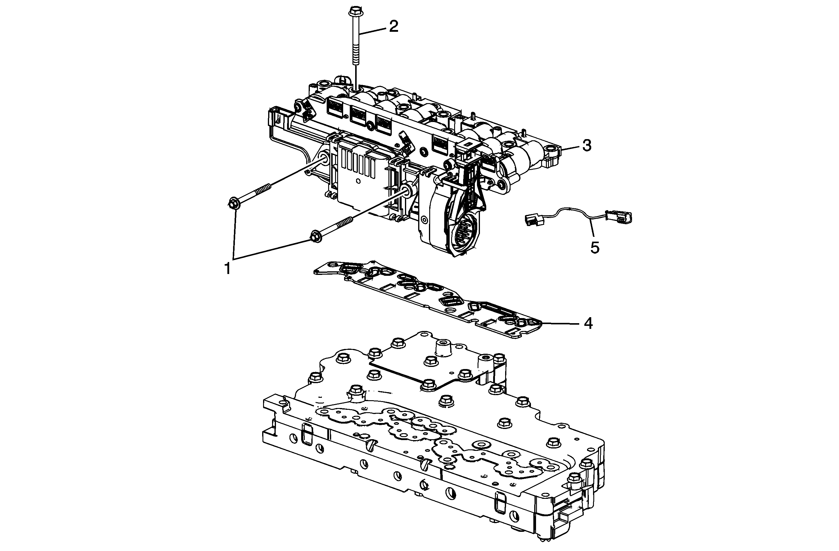
Control Solenoid Valve and Valve Body Assembly Disassemble

Callout | Component Name |
|---|---|
1 | Control Solenoid Valve Heat Sink (w/Body and TCM) Bolt M5 x .8 x 53 (Qty: 2) |
2 | Control Valve Lower Body Bolt M6 x 1.0 x 55 (Qty: 9) |
3 | Control Solenoid (w/Body and TCM) Valve Assembly |
4 | Control Valve Channel Plate Spacer Plate Gasket Caution: Use care when handling the control valve body assembly. If dropped, damage to the control solenoid valve body assembly internal components, including the transmission control module (TCM), may result. Caution: Discard the filter plate. Replace with a NEW filter plate. Reusing an old filter plate may cause damage to the control solenoid valve assembly. |
5 | A/Trans Wiring Harness Assembly |
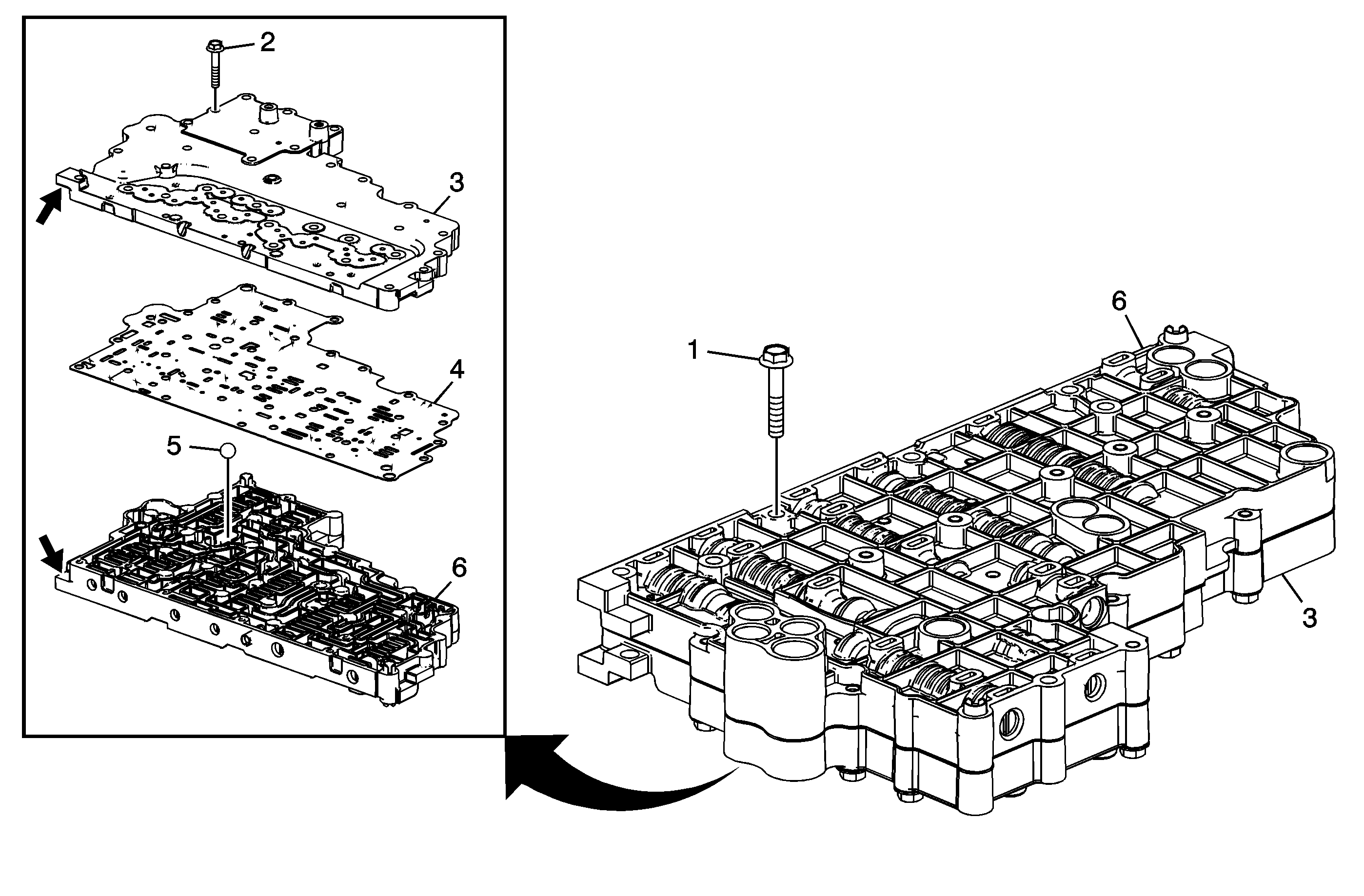
Valve Assembly and Transfer Plate Disassemble

Callout | Component Name | ||||||
|---|---|---|---|---|---|---|---|
1 | Control Valve Channel Plate Bolt M6 x1.0 x 35 (Qty: 3) | ||||||
2 | Control Valve Channel Plate Bolt M6 x 1.0 x 35.0 (Qty: 17) | ||||||
3 | Control Valve Channel Plate Tip | ||||||
4 | Control Valve Body Spacer (w/Gasket) Plate Assembly Caution: Do not use the old spacer plate. Install a NEW spacer plate. Reusing an old spacer plate may cause internal transmission leaks and transmission damage. | ||||||
5 | A/Trans Fluid Pump Ball Check Valve Tip
| ||||||
6 | Control Valve Upper Body Assembly |
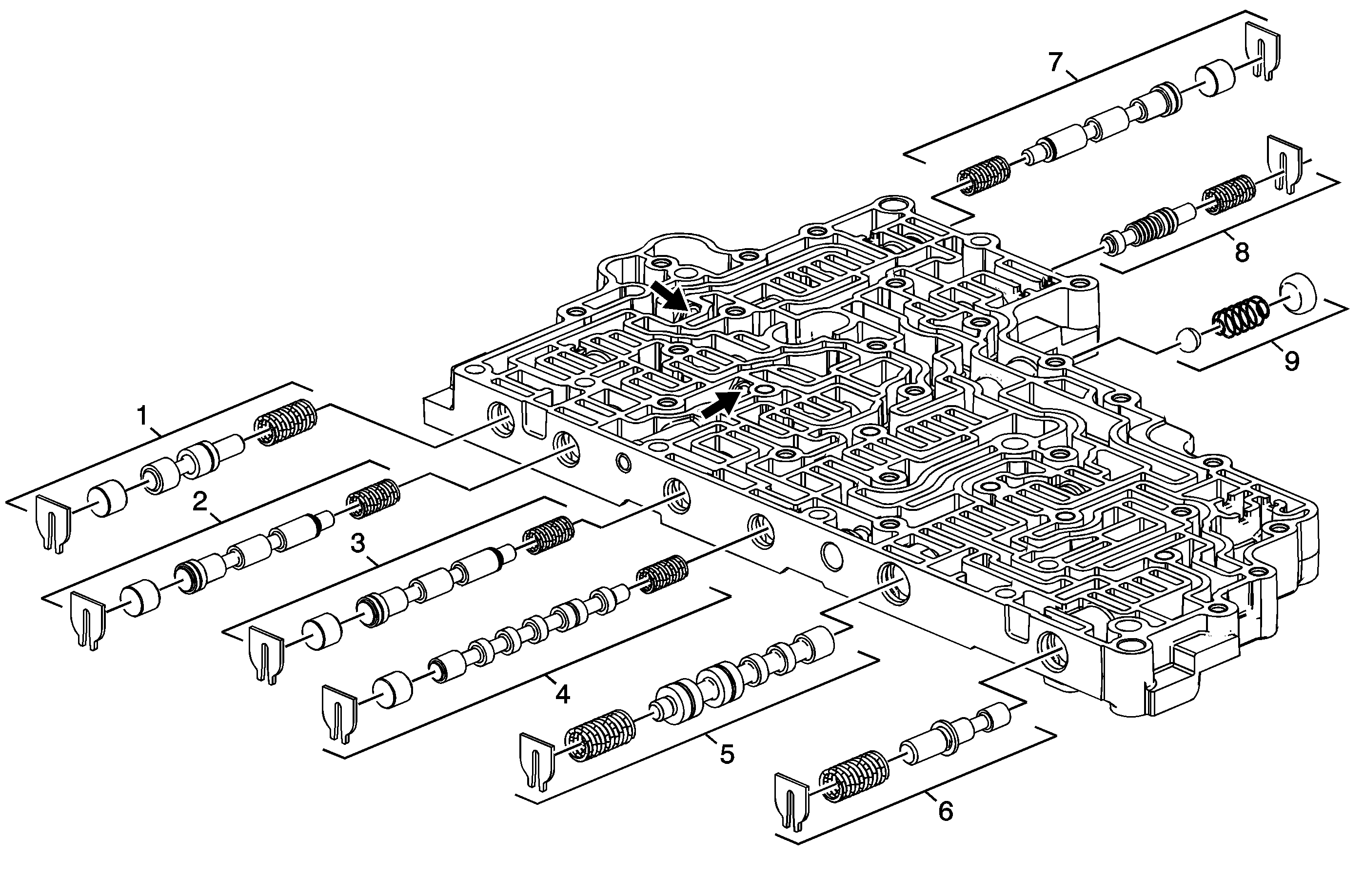
Valve Assembly Overhaul

Callout | Component Name |
|---|---|
|
Warning: Valve springs can be tightly compressed. Use care when removing retainers and plugs. Personal injury could result. Preliminary Procedures
| |
1 | Auxiliary Line Boost Valve Train |
2 | 1-3 Clutch Regulator Valve Train |
3 | Hybrid Direct, 2-3-4 Clutch Regulator Valve Train |
4 | Shift Solenoid Valve Train - Mode A |
5 | Shift Solenoid Valve Train - Mode B |
6 | Actuator Feed Limit Valve Train |
7 | Hybrid Low, 1-2 Clutch Regulator Valve |
8 | Hybrid Low, 1-2 Clutch Boost Valve Train |
9 | Clutch Piston Exhaust Blowoff Ball Valve Train |
