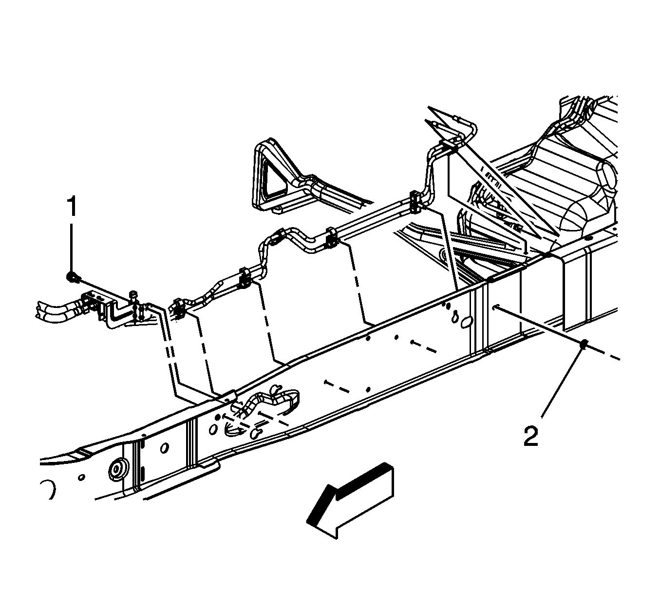
Fuel Hose/Pipes Replacement - Chassis 2500/3500 Regular Cab
Removal Procedure
- Relieve the fuel system pressure. Refer to the Fuel Pressure Relief.
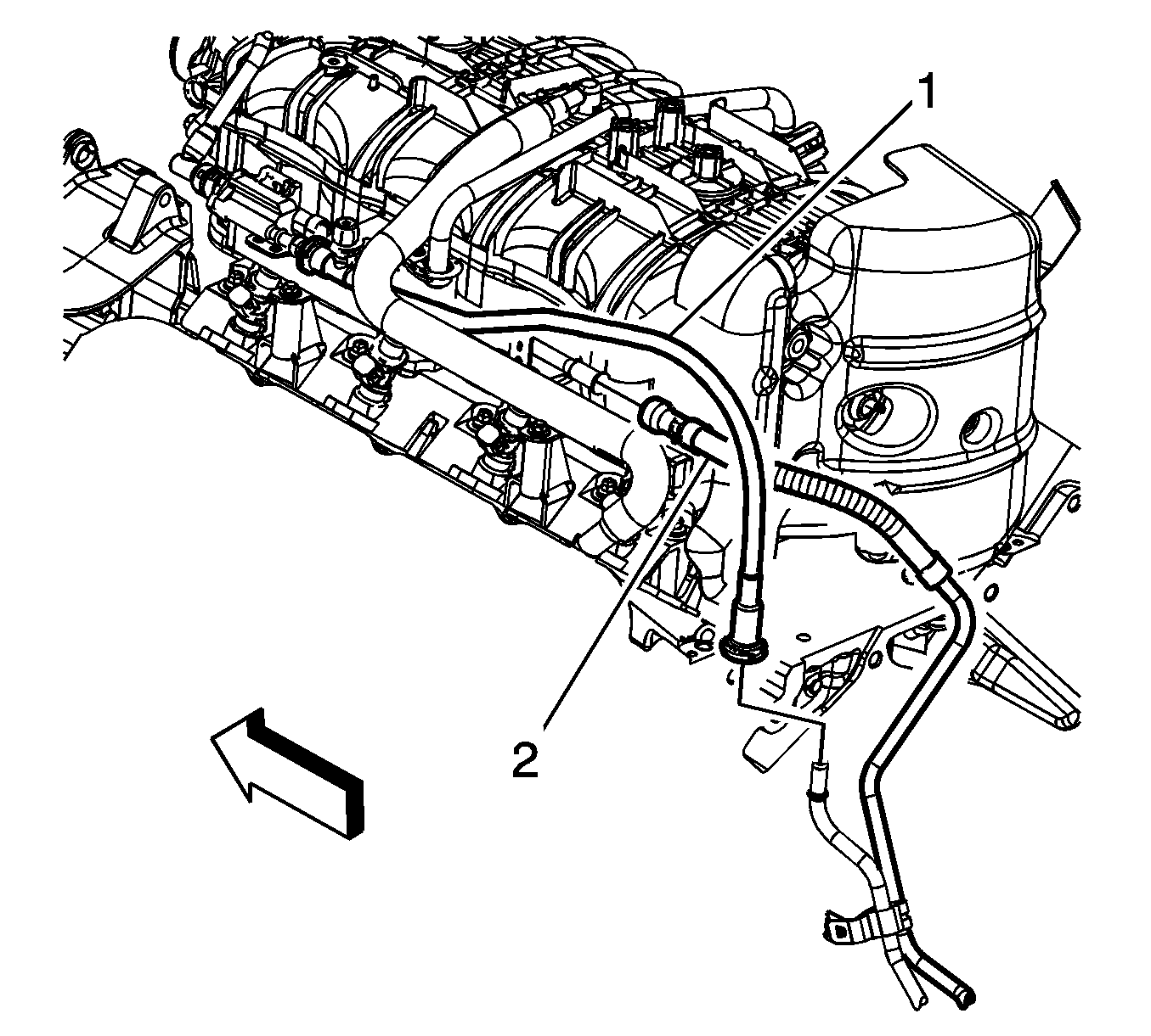
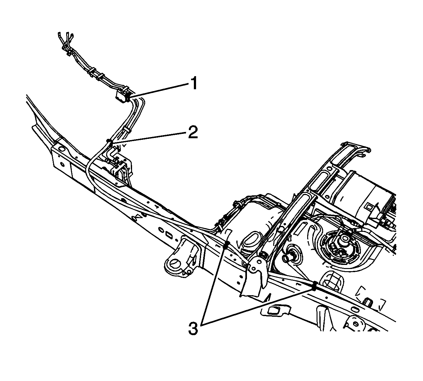
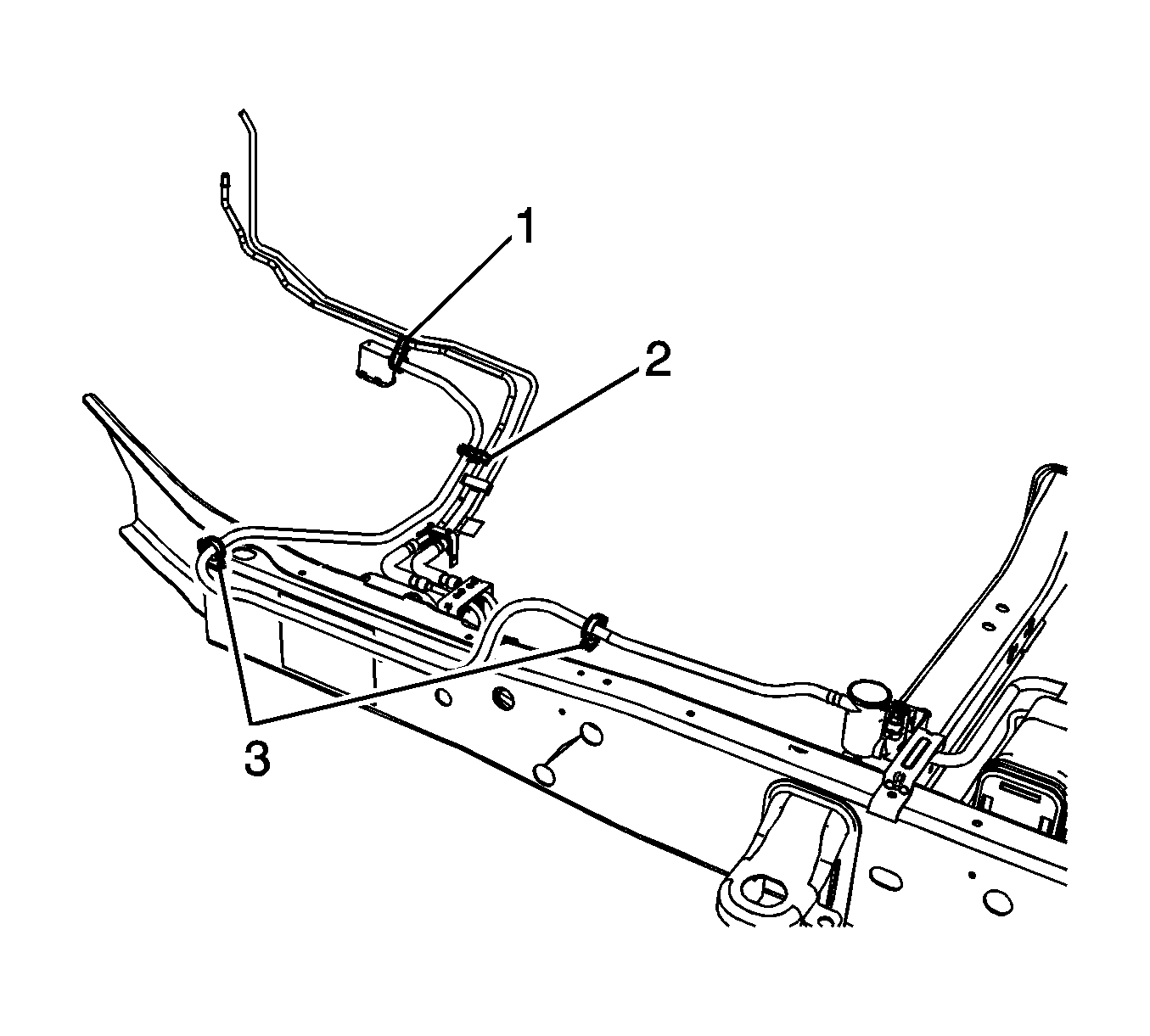
- Disconnect the engine evaporative emission (EVAP) line (1) quick connect fitting from the chassis EVAP line. Refer to Plastic Collar Quick Connect Fitting Service.
- Disconnect the fuel feed line quick connect fitting (2) from the fuel rail. Refer to Metal Collar Quick Connect Fitting Service.
- Cap the fuel rail and EVAP pipes.
- Raise and support the vehicle. Refer to Lifting and Jacking the Vehicle.
- Unbolt and reposition the front propeller shaft, if required. Refer to Front Propeller Shaft Replacement.
- Unbolt and reposition the brake pressure modulator valve (BPMV). Refer to Brake Pressure Modulator Valve Replacement.
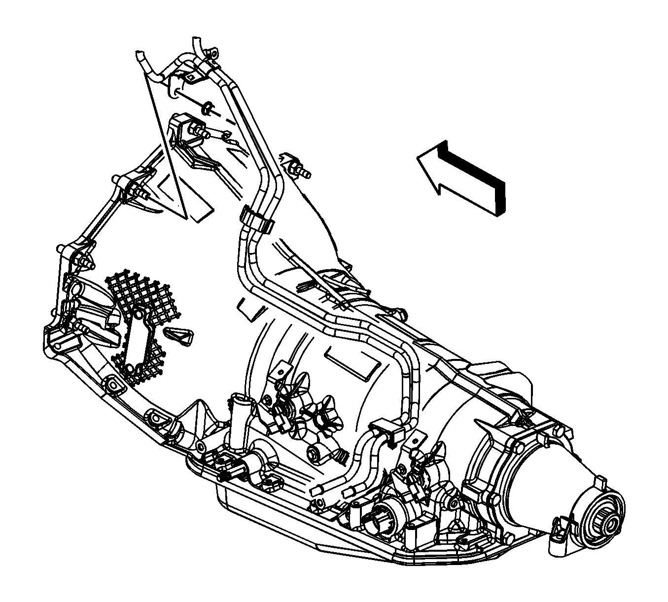
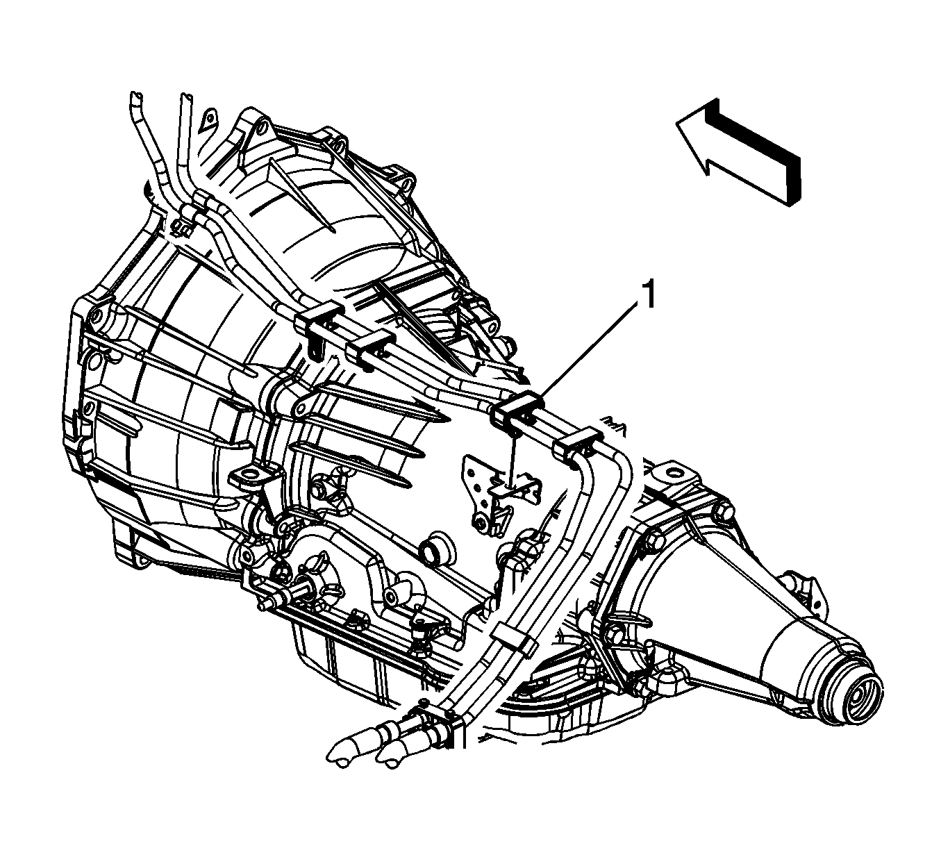
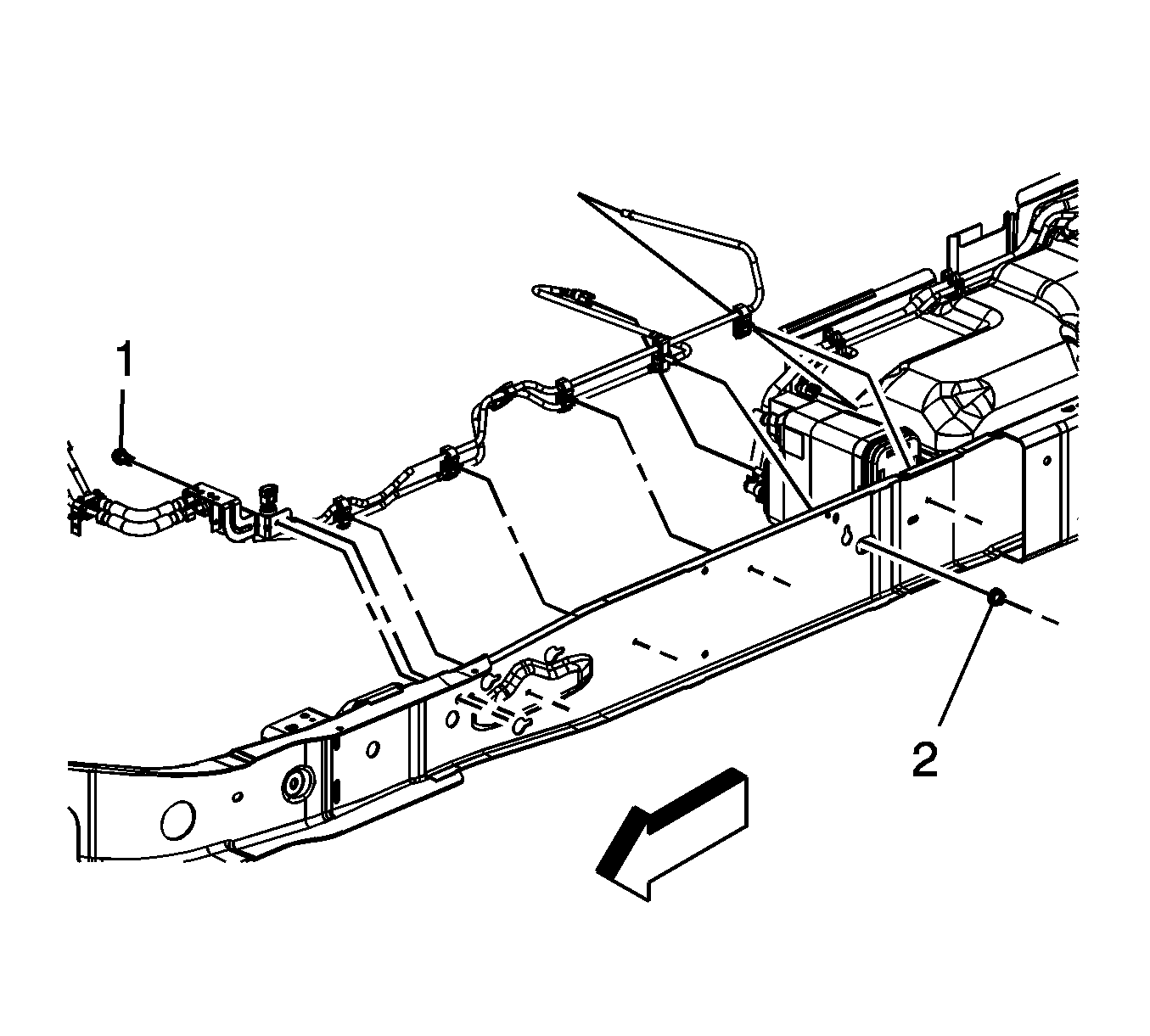
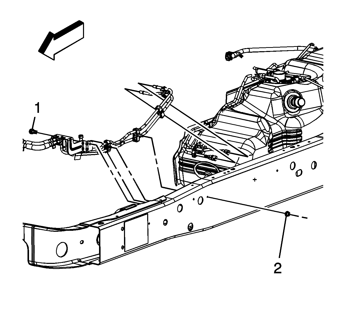
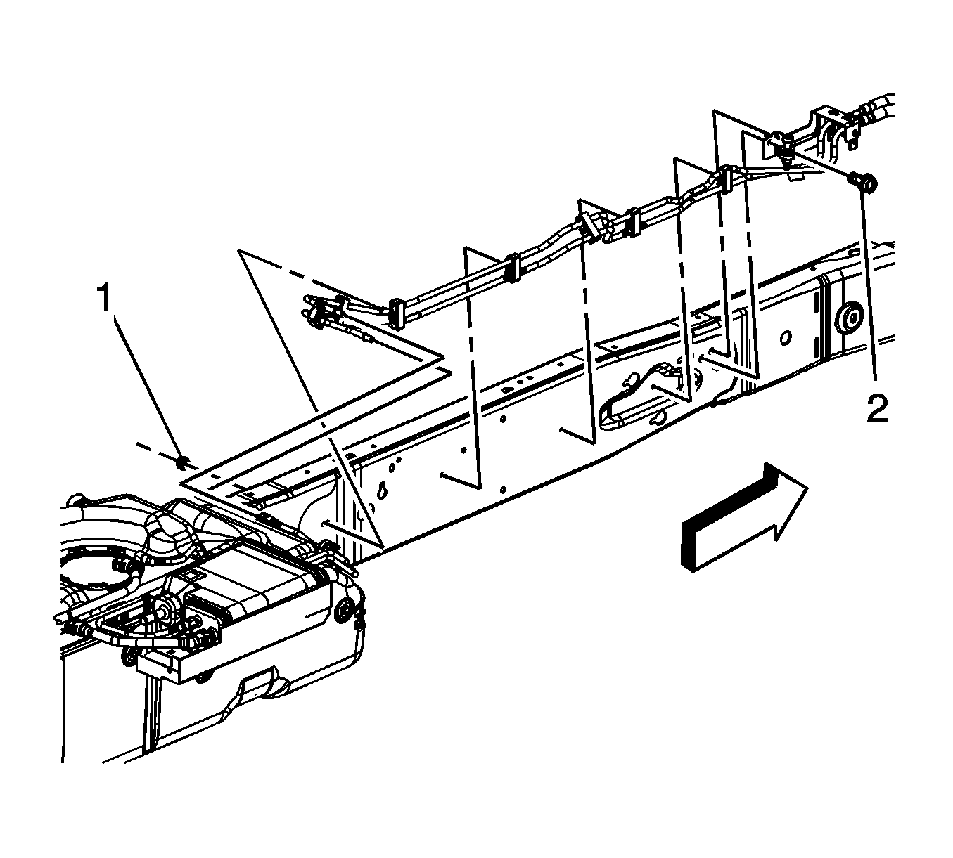
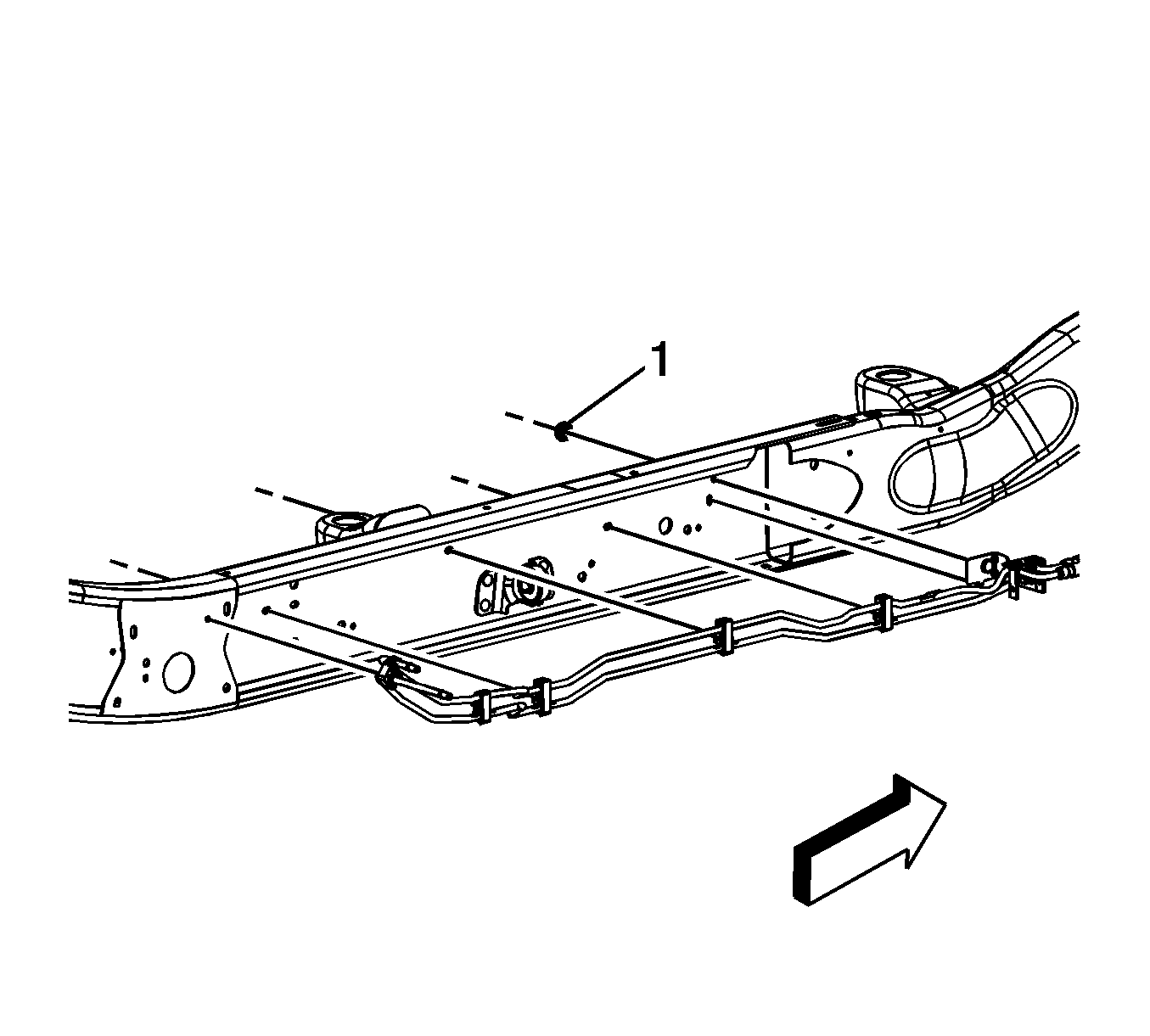
- Remove the fuel pipe bracket nut from the bellhousing stud.
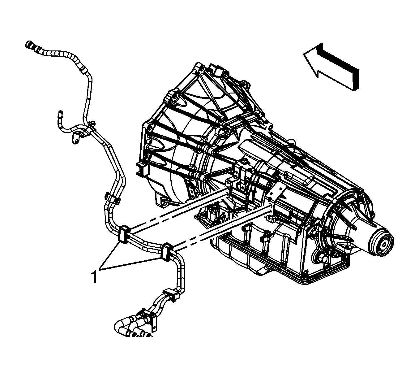
- Remove the fuel line clips (1) from the bracket on the automatic transmission.
- If equipped with 4-wheel drive (4WD), remove the fuel hose/pipe clip from the bracket on the transfer case.
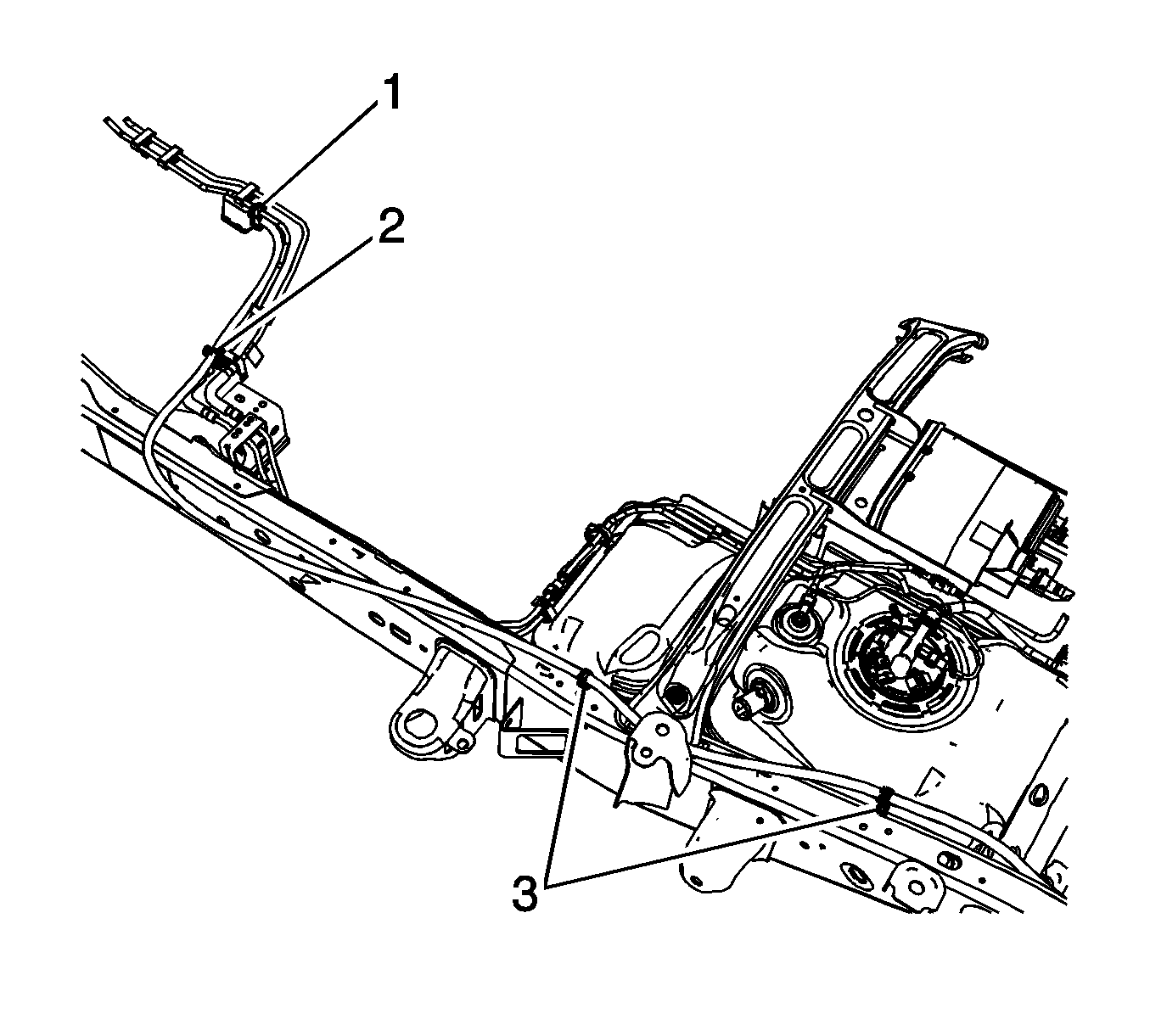
- Remove the EVAP canister vent solenoid clip (1) from the chassis EVAP line and secure out of the way.
- Remove the EVAP canister vent solenoid pipe clip (2) from the chassis EVAP line.
- Disconnect the fuel tank fuel feed line quick connect fitting from the chassis line. Refer to Plastic Collar Quick Connect Fitting Service.
- Disconnect the fuel tank EVAP line quick connect fitting from the chassis line. Refer to Plastic Collar Quick Connect Fitting Service.
- Cap the fuel and EVAP lines in order to prevent possible fuel and/or EVAP system contamination.
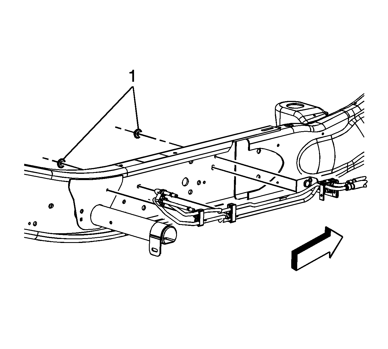
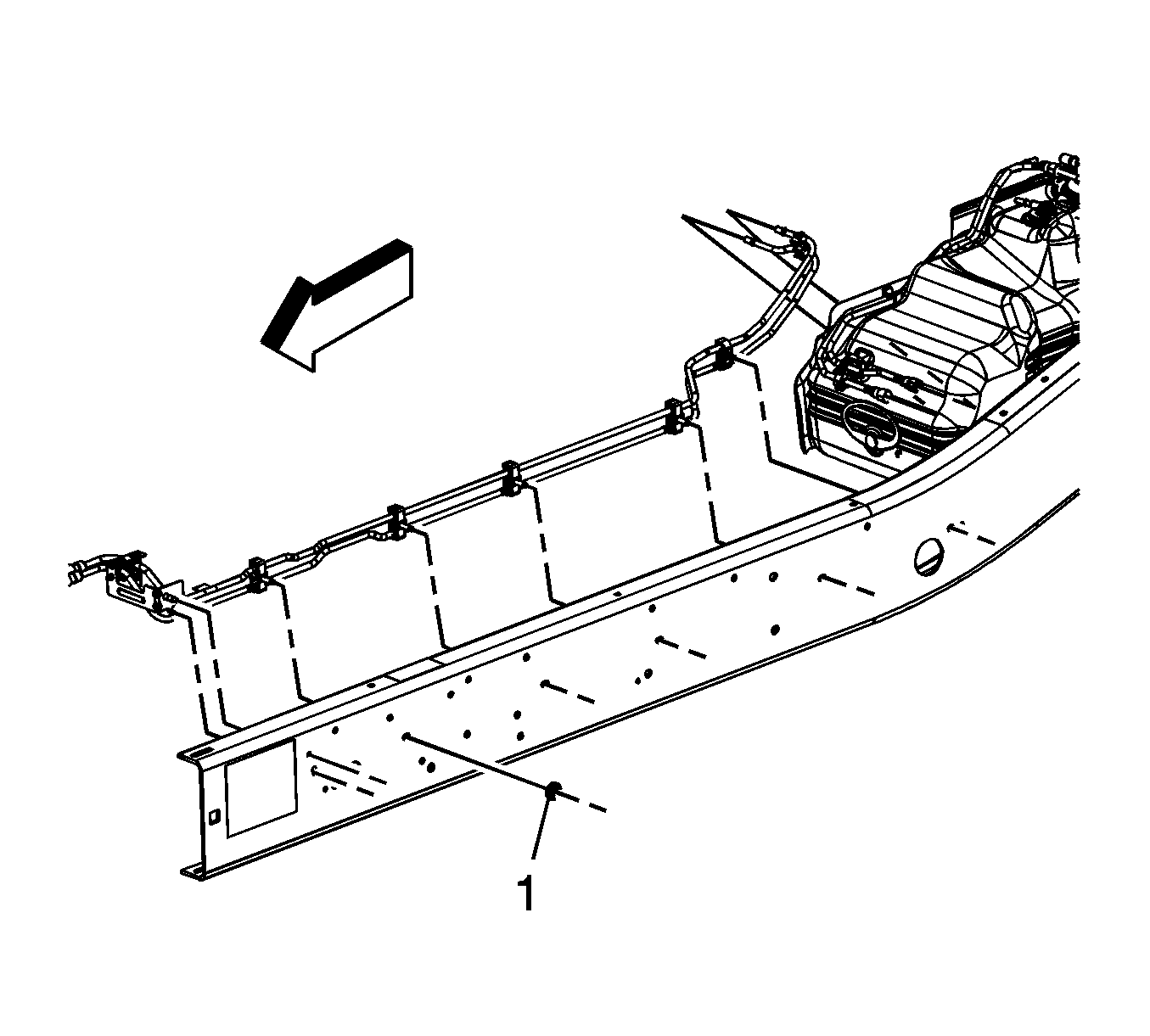
- Remove the fuel/EVAP line clip nuts (1).
- Remove the fuel/EVAP line clips from the frame and crossmember.
- Remove the fuel/EVAP line assembly from the vehicle.
Note: Clean all fuel and evaporative emission (EVAP) lines connections and surrounding areas prior to disconnecting the lines in order to avoid possible fuel and/or EVAP system contamination.
Installation Procedure
- Position and install the fuel/EVAP line assembly to the vehicle.
- Install the fuel/EVAP line bracket locator tab to the frame.
- Install the fuel/EVAP line clips to the frame and crossmember.
- Install the fuel/EVAP line clip nuts (2).
- Remove the caps from the fuel and EVAP lines.
- Connect the fuel tank EVAP line quick connect fitting to the chassis line. Refer to Plastic Collar Quick Connect Fitting Service.
- Connect the fuel tank fuel feed line quick connect fitting to the chassis line. Refer to Plastic Collar Quick Connect Fitting Service.
- Unsecure and position the EVAP canister vent solenoid clip (1) to the chassis EVAP line.
- Install the EVAP canister vent solenoid pipe clip (2) to the chassis EVAP line.
- If equipped with 4WD, install the fuel hose/pipe clip to the bracket on the transfer case.
- Install the fuel line clip to the bracket on the automatic transmission.
- Install the fuel pipe bracket nut to the bellhousing stud.
- Position and install the BPMV. Refer to Brake Pressure Modulator Valve Replacement.
- Position and install the front propeller shaft, if required. Refer to Front Propeller Shaft Replacement.
- Lower the vehicle.
- Remove the caps from the fuel rail and EVAP line.
- Connect the EVAP line (1) quick connect fitting to the chassis EVAP line. Refer to Plastic Collar Quick Connect Fitting Service.
- Connect the fuel feed line (2) quick connect fitting to the fuel rail. Refer to Metal Collar Quick Connect Fitting Service.
- Install the fuel fill cap.
- Connect the negative battery cable. Refer to Battery Negative Cable Disconnection and Connection.
- Use the following procedure in order to inspect for leaks:
- Install the intake manifold sight shield. Refer to Upper Intake Manifold Sight Shield Replacement.
Caution: Refer to Fastener Caution in the Preface section.
Tighten
Tighten the bolt to 20 N·m (15 lb ft).
Tighten
Tighten the nut to 25 N·m (18 lb ft).
| 21.1. | Turn the ignition ON, with the engine OFF, for 2 seconds. |
| 21.2. | Turn the ignition OFF for 10 seconds. |
| 21.3. | Turn the ignition ON, with the engine OFF. |
| 21.4. | Inspect for fuel leaks. |
Fuel Hose/Pipes Replacement - Chassis 2500/3500 Crew Cab
Removal Procedure
- Relieve the fuel system pressure. Refer to the Fuel Pressure Relief.
- Disconnect the engine evaporative emission (EVAP) line (1) quick connect fitting from the chassis EVAP line. Refer to Plastic Collar Quick Connect Fitting Service.
- Disconnect the fuel feed line quick connect fitting (2) from the fuel rail. Refer to Metal Collar Quick Connect Fitting Service.
- Cap the fuel rail and EVAP pipes.
- Raise and support the vehicle. Refer to Lifting and Jacking the Vehicle.
- Unbolt and reposition the front propeller shaft, if required. Refer to Front Propeller Shaft Replacement.
- Unbolt and reposition the brake pressure modulator valve (BPMV). Refer to Brake Pressure Modulator Valve Replacement.
- Remove the fuel pipe bracket nut from the bellhousing stud.
- Remove the fuel line clips (1) from the bracket on the automatic transmission.
- If equipped with 4-wheel drive (4WD), remove the fuel hose/pipe clip from the bracket on the transfer case.
- Remove the EVAP canister vent solenoid clip (1) from the chassis EVAP line and secure out of the way.
- Remove the EVAP canister vent solenoid pipe clip (2) from the chassis EVAP line.
- Disconnect the fuel tank fuel feed line quick connect fitting from the chassis line. Refer to Plastic Collar Quick Connect Fitting Service.
- Disconnect the fuel tank EVAP line quick connect fitting from the chassis line. Refer to Plastic Collar Quick Connect Fitting Service.
- Cap the fuel and EVAP lines in order to prevent possible fuel and/or EVAP system contamination.
- Remove the fuel/EVAP line clip nuts (1).
- Remove the fuel/EVAP line clips from the frame and crossmember.
- Remove the fuel/EVAP line assembly from the vehicle.
Note: Clean all fuel and evaporative emission (EVAP) lines connections and surrounding areas prior to disconnecting the lines in order to avoid possible fuel and/or EVAP system contamination.
Installation Procedure
- Position and install the fuel/EVAP line assembly to the vehicle.
- Install the fuel/EVAP line bracket locator tab to the frame.
- Install the fuel/EVAP line clips to the frame and crossmember.
- Install the fuel/EVAP line clip nuts (2).
- Remove the caps from the fuel and EVAP lines.
- Connect the fuel tank EVAP line quick connect fitting to the chassis line. Refer to Plastic Collar Quick Connect Fitting Service.
- Connect the fuel tank fuel feed line quick connect fitting to the chassis line. Refer to Plastic Collar Quick Connect Fitting Service.
- Unsecure and position the EVAP canister vent solenoid clip (1) to the chassis EVAP line.
- Install the EVAP canister vent solenoid pipe clip (2) from the chassis EVAP line.
- If equipped with 4WD, install the fuel hose/pipe clip to the bracket on the transfer case.
- Install the fuel line clip to the bracket on the automatic transmission.
- Install the fuel pipe bracket nut to the bellhousing stud.
- Position and install the BPMV. Refer to Brake Pressure Modulator Valve Replacement.
- Position and install the front propeller shaft, if required. Refer to Front Propeller Shaft Replacement.
- Lower the vehicle.
- Remove the caps from the fuel rail and EVAP line.
- Connect the EVAP line (1) quick connect fitting to the chassis EVAP line. Refer to Plastic Collar Quick Connect Fitting Service.
- Connect the fuel feed line (2) quick connect fitting to the fuel rail. Refer to Metal Collar Quick Connect Fitting Service.
- Install the fuel fill cap.
- Connect the negative battery cable. Refer to Battery Negative Cable Disconnection and Connection.
- Use the following procedure in order to inspect for leaks:
- Install the intake manifold sight shield. Refer to Upper Intake Manifold Sight Shield Replacement.
Caution: Refer to Fastener Caution in the Preface section.
Tighten
Tighten the bolt to 20 N·m (15 lb ft).
Tighten
Tighten the nut to 25 N·m (18 lb ft).
| 21.1. | Turn the ignition ON, with the engine OFF, for 2 seconds. |
| 21.2. | Turn the ignition OFF for 10 seconds. |
| 21.3. | Turn the ignition ON, with the engine OFF. |
| 21.4. | Inspect for fuel leaks. |
Fuel Hose/Pipes Replacement - Chassis 1500 Extended/Crew Cab
Removal Procedure
- Relieve the fuel system pressure. Refer to the Fuel Pressure Relief.
- Disconnect the engine evaporative emission (EVAP) line (1) quick connect fitting from the chassis EVAP line. Refer to Plastic Collar Quick Connect Fitting Service.
- Disconnect the fuel feed line quick connect fitting (2) from the fuel rail. Refer to Metal Collar Quick Connect Fitting Service.
- Cap the fuel rail and EVAP pipes.
- Raise and support the vehicle. Refer to Lifting and Jacking the Vehicle.
- Unbolt and reposition the front propeller shaft, if required. Refer to Front Propeller Shaft Replacement.
- Unbolt and reposition the brake pressure modulator valve (BPMV). Refer to Brake Pressure Modulator Valve Replacement.
- Remove the fuel pipe bracket nut from the bellhousing stud.
- Remove the fuel line clip from the bracket on the automatic transmission.
- If equipped with 4-wheel drive (4WD), remove the fuel hose/pipe clip from the bracket on the transfer case.
- Remove the EVAP canister vent solenoid clip (1) from the chassis EVAP line and secure out of the way.
- Remove the EVAP canister vent solenoid pipe clip (2) from the chassis line.
- Disconnect the fuel tank fuel feed line quick connect fitting from the chassis line. Refer to Plastic Collar Quick Connect Fitting Service.
- Disconnect the chassis EVAP line quick connect fitting from the EVAP canister. Refer to Plastic Collar Quick Connect Fitting Service.
- Cap the fuel and EVAP lines in order to prevent possible fuel and/or EVAP system contamination.
- Remove the fuel line bracket bolt (1).
- Remove the fuel/EVAP line clip nut (2).
- Remove the fuel/EVAP line clips from the frame and crossmember.
- Remove the fuel/EVAP line assembly from the vehicle.
Note: Clean all fuel and evaporative emission (EVAP) lines connections and surrounding areas prior to disconnecting the lines in order to avoid possible fuel and/or EVAP system contamination.
Installation Procedure
- Position and install the fuel/EVAP line assembly to the vehicle.
- Install the fuel/EVAP line bracket locator tab to the frame.
- Install the fuel/EVAP line clips to the frame and crossmember.
- Install the fuel/EVAP line bracket bolt (1).
- Install the fuel/EVAP line clip nut (2).
- Remove the caps from the fuel and EVAP lines.
- Connect the chassis EVAP line quick connect fitting to the EVAP canister. Refer to Plastic Collar Quick Connect Fitting Service.
- Connect the fuel tank fuel feed line quick connect fitting to the chassis line. Refer to Plastic Collar Quick Connect Fitting Service.
- Unsecure and position the EVAP canister vent solenoid clip (1) to the chassis EVAP line.
- Install the EVAP canister vent solenoid pipe clip (2) to the chassis line.
- If equipped with 4WD, install the fuel hose/pipe clip to the bracket on the transfer case.
- Install the fuel line clip to the bracket on the automatic transmission.
- Install the fuel pipe bracket nut to the bellhousing stud.
- Position and install the BPMV. Refer to Brake Pressure Modulator Valve Replacement.
- Position and install the front propeller shaft, if required. Refer to Front Propeller Shaft Replacement.
- Lower the vehicle.
- Remove the caps from the fuel rail and EVAP line.
- Connect the EVAP line (1) quick connect fitting to the chassis EVAP line. Refer to Plastic Collar Quick Connect Fitting Service.
- Connect the fuel feed line (2) quick connect fitting to the fuel rail. Refer to Metal Collar Quick Connect Fitting Service.
- Install the fuel fill cap.
- Connect the negative battery cable. Refer to Battery Negative Cable Disconnection and Connection.
- Use the following procedure in order to inspect for leaks:
- Install the intake manifold sight shield. Refer to Upper Intake Manifold Sight Shield Replacement.
Caution: Refer to Fastener Caution in the Preface section.
Tighten
Tighten the bolt to 9 N·m (80 lb in).
Tighten
Tighten the bolt to 20 N·m (15 lb ft).
Tighten
Tighten the nut to 25 N·m (18 lb ft).
| 22.1. | Turn the ignition ON, with the engine OFF, for 2 seconds. |
| 22.2. | Turn the ignition OFF for 10 seconds. |
| 22.3. | Turn the ignition ON, with the engine OFF. |
| 22.4. | Inspect for fuel leaks. |
Fuel Hose/Pipes Replacement - Chassis 1500 Regular Cab
Removal Procedure
- Relieve the fuel system pressure. Refer to the Fuel Pressure Relief.
- Disconnect the engine evaporative emission (EVAP) line (1) quick connect fitting from the chassis EVAP line. Refer to Plastic Collar Quick Connect Fitting Service.
- Disconnect the fuel feed line quick connect fitting (2) from the fuel rail. Refer to Metal Collar Quick Connect Fitting Service.
- Cap the fuel rail and EVAP pipes.
- Raise and support the vehicle. Refer to Lifting and Jacking the Vehicle.
- Unbolt and reposition the front propeller shaft, if required. Refer to Front Propeller Shaft Replacement.
- Remove the fuel pipe bracket nut from the bellhousing stud.
- Remove the fuel line clip from the bracket on the automatic transmission.
- If equipped with 4-wheel drive (4WD), remove the fuel hose/pipe clip from the bracket on the transfer case.
- Remove the EVAP canister vent solenoid clip (1) from the chassis EVAP line and secure out of the way.
- Remove the EVAP canister vent solenoid pipe clip (2) from the chassis EVAP line.
- Disconnect the fuel tank EVAP line quick connect fitting from the chassis line. Refer to Plastic Collar Quick Connect Fitting Service.
- Disconnect the fuel tank fuel feed line quick connect fitting from the chassis line. Refer to Plastic Collar Quick Connect Fitting Service.
- Cap the fuel and EVAP lines in order to prevent possible fuel and/or EVAP system contamination.
- Remove the fuel line bracket bolt (1).
- Remove the fuel/EVAP line clip nut (2).
- Remove the fuel/EVAP line clips from the frame and crossmember.
- Remove the fuel/EVAP line assembly from the vehicle.
Note: Clean all fuel and evaporative emission (EVAP) lines connections and surrounding areas prior to disconnecting the lines in order to avoid possible fuel and/or EVAP system contamination.
Installation Procedure
- Position and install the fuel/EVAP line assembly to the vehicle.
- Install the fuel/EVAP line bracket locator tab to the frame.
- Install the fuel/EVAP line clips to the frame and crossmember.
- Install the fuel/EVAP line bracket bolt (1).
- Install the fuel/EVAP line clip nut (2).
- Remove the caps from the fuel and EVAP lines.
- Connect the fuel tank EVAP line quick connect fitting to the chassis line. Refer to Plastic Collar Quick Connect Fitting Service.
- Connect the fuel tank fuel feed line quick connect fitting to the chassis line. Refer to Plastic Collar Quick Connect Fitting Service.
- Unscure and position the EVAP canister vent solenoid clip (1) to the chassis EVAP line.
- Install the EVAP canister vent solenoid pipe clip (2) to the chassis EVAP line.
- If equipped with 4WD, install the fuel hose/pipe clip to the bracket on the transfer case.
- Install the fuel line clip to the bracket on the automatic transmission.
- Install the fuel pipe bracket nut to the bellhousing stud.
- Position and install the front propeller shaft, if required. Refer to Front Propeller Shaft Replacement.
- Lower the vehicle.
- Remove the caps from the fuel rail and EVAP line.
- Connect the EVAP line (1) quick connect fitting to the chassis EVAP line. Refer to Plastic Collar Quick Connect Fitting Service.
- Connect the fuel feed line (2) quick connect fitting to the fuel rail. Refer to Metal Collar Quick Connect Fitting Service.
- Install the fuel fill cap.
- Connect the negative battery cable. Refer to Battery Negative Cable Disconnection and Connection.
- Use the following procedure in order to inspect for leaks:
- Install the intake manifold sight shield. Refer to Upper Intake Manifold Sight Shield Replacement.
Caution: Refer to Fastener Caution in the Preface section.
Tighten
Tighten the bolt to 9 N·m (80 lb in).
Tighten
Tighten the bolt to 20 N·m (15 lb ft).
Tighten
Tighten the nut to 25 N·m (18 lb ft).
| 21.1. | Turn the ignition ON, with the engine OFF, for 2 seconds. |
| 21.2. | Turn the ignition OFF for 10 seconds. |
| 21.3. | Turn the ignition ON, with the engine OFF. |
| 21.4. | Inspect for fuel leaks. |
Fuel Hose/Pipes Replacement - Chassis 1500 Extended Cab - w/8 Ft Bed
Removal Procedure
- Relieve the fuel system pressure. Refer to the Fuel Pressure Relief.
- Disconnect the engine evaporative emission (EVAP) line (1) quick connect fitting from the chassis EVAP line. Refer to Plastic Collar Quick Connect Fitting Service.
- Disconnect the fuel feed line quick connect fitting (2) from the fuel rail. Refer to Metal Collar Quick Connect Fitting Service.
- Cap the fuel rail and EVAP pipes.
- Raise and support the vehicle. Refer to Lifting and Jacking the Vehicle.
- Unbolt and reposition the front propeller shaft, if required. Refer to Front Propeller Shaft Replacement.
- Remove the fuel pipe bracket nut from the bellhousing stud.
- Remove the fuel line clip from the bracket on the automatic transmission.
- If equipped with 4-wheel drive (4WD), remove the fuel hose/pipe clip from the bracket on the transfer case.
- Remove the EVAP canister vent solenoid clip (1) from the chassis EVAP line and secure out of the way.
- Remove the EVAP canister vent solenoid pipe clip (2) from the chassis EVAP line.
- If equipped with 2-wheel drive (2WD) perform the following steps, disconnect the fuel tank fuel feed line quick connect fitting from the chassis line. Refer to Plastic Collar Quick Connect Fitting Service.
- Disconnect the fuel tank EVAP line quick connect fitting from the chassis line. Refer to Plastic Collar Quick Connect Fitting Service.
- Cap the fuel and EVAP lines in order to prevent possible fuel and/or EVAP system contamination.
- Remove the fuel line bracket bolt (2).
- Remove the fuel/EVAP line clip nut (1).
- Remove the fuel/EVAP line clips from the frame and crossmember.
- Remove the fuel/EVAP line assembly from the vehicle.
- If equipped with 4WD perform the following steps, disconnect the fuel tank fuel feed line quick connect fitting from the chassis line. Refer to Plastic Collar Quick Connect Fitting Service.
- Disconnect the fuel tank EVAP line quick connect fitting from the chassis line. Refer to Plastic Collar Quick Connect Fitting Service.
- Cap the fuel and EVAP lines in order to prevent possible fuel and/or EVAP system contamination.
- Remove the fuel line bracket bolt (1).
- Remove the fuel/EVAP line clip nut (2).
- Remove the fuel/EVAP line clips from the frame and crossmember.
- Remove the fuel/EVAP line assembly from the vehicle.
Note: Clean all fuel and evaporative emission (EVAP) lines connections and surrounding areas prior to disconnecting the lines in order to avoid possible fuel and/or EVAP system contamination.
Installation Procedure
- If equipped with 4WD perfrom the following steps, position and install the fuel/EVAP line assembly to the vehicle.
- Install the fuel/EVAP line bracket locator tab to the frame.
- Install the fuel/EVAP line clips to the frame and crossmember.
- Install the fuel/EVAP line bracket bolt (1).
- Install the fuel/EVAP line clip nut (2).
- Remove the caps from the fuel and EVAP lines.
- Connect the fuel tank EVAP line quick connect fitting to the chassis line. Refer to Plastic Collar Quick Connect Fitting Service.
- Connect the fuel tank fuel feed line quick connect fitting to the chassis line. Refer to Plastic Collar Quick Connect Fitting Service.
- If equipped with 2WD perfrom the following steps, position and install the fuel/EVAP line assembly to the vehicle.
- Install the fuel/EVAP line bracket locator tab to the frame.
- Install the fuel/EVAP line clips to the frame and crossmember.
- Install the fuel/EVAP line bracket bolt (2).
- Install the fuel/EVAP line clip nut (1).
- Remove the caps from the fuel and EVAP lines.
- Connect the fuel tank EVAP line quick connect fitting to the chassis line. Refer to Plastic Collar Quick Connect Fitting Service.
- Connect the fuel tank fuel feed line quick connect fitting to the chassis line. Refer to Plastic Collar Quick Connect Fitting Service.
- Unsecure and position the EVAP canister vent solenoid clip (1) to the chassis EVAP line.
- Install the EVAP canister vent solenoid pipe clip (2) from the chassis EVAP line.
- If equipped with 4WD, install the fuel hose/pipe clip to the bracket on the transfer case.
- Install the fuel line clip to the bracket on the automatic transmission.
- Install the fuel pipe bracket nut to the bellhousing stud.
- Position and install the front propeller shaft, if required. Refer to Front Propeller Shaft Replacement.
- Lower the vehicle.
- Remove the caps from the fuel rail and EVAP line.
- Connect the EVAP line (1) quick connect fitting to the chassis EVAP line. Refer to Plastic Collar Quick Connect Fitting Service.
- Connect the fuel feed line (2) quick connect fitting to the fuel rail. Refer to Metal Collar Quick Connect Fitting Service.
- Install the fuel fill cap.
- Connect the negative battery cable. Refer to Battery Negative Cable Disconnection and Connection.
- Use the following procedure in order to inspect for leaks:
- Install the intake manifold sight shield. Refer to Upper Intake Manifold Sight Shield Replacement.
Caution: Refer to Fastener Caution in the Preface section.
Tighten
Tighten the bolt to 9 N·m (80 lb in).
Tighten
Tighten the bolt to 20 N·m (15 lb ft).
Tighten
Tighten the bolt to 9 N·m (80 lb in).
Tighten
Tighten the bolt to 20 N·m (15 lb ft).
Tighten
Tighten the nut to 25 N·m (18 lb ft).
| 29.1. | Turn the ignition ON, with the engine OFF, for 2 seconds. |
| 29.2. | Turn the ignition OFF for 10 seconds. |
| 29.3. | Turn the ignition ON, with the engine OFF. |
| 29.4. | Inspect for fuel leaks. |
Fuel Hose/Pipes Replacement - Chassis 2500/3500 Extended Cab
Removal Procedure
- Relieve the fuel system pressure. Refer to the Fuel Pressure Relief.
- Disconnect the engine evaporative emission (EVAP) line (1) quick connect fitting from the chassis EVAP line. Refer to Plastic Collar Quick Connect Fitting Service.
- Disconnect the fuel feed line quick connect fitting (2) from the fuel rail. Refer to Metal Collar Quick Connect Fitting Service.
- Cap the fuel rail and EVAP pipes.
- Raise and support the vehicle. Refer to Lifting and Jacking the Vehicle.
- Unbolt and reposition the front propeller shaft, if required. Refer to Front Propeller Shaft Replacement.
- Remove the fuel pipe bracket nut from the bellhousing stud.
- Remove the fuel line clips (1) from the bracket on the automatic transmission.
- If equipped with 4-wheel drive (4WD), remove the fuel hose/pipe clip from the bracket on the transfer case.
- Remove the EVAP canister vent solenoid clip (1) from the chassis EVAP line and secure out of the way.
- Remove the EVAP canister vent solenoid pipe clip (2) from the chassis EVAP line.
- Disconnect the fuel tank fuel feed line quick connect fitting from the chassis line. Refer to Plastic Collar Quick Connect Fitting Service.
- Disconnect the fuel tank EVAP line quick connect fitting from the chassis line. Refer to Plastic Collar Quick Connect Fitting Service.
- Cap the fuel and EVAP lines in order to prevent possible fuel and/or EVAP system contamination.
- Remove the fuel/EVAP line clip nuts (1).
- Remove the fuel/EVAP line clips from the frame and crossmember.
- Remove the fuel/EVAP line assembly from the vehicle.
Note: Clean all fuel and evaporative emission (EVAP) lines connections and surrounding areas prior to disconnecting the lines in order to avoid possible fuel and/or EVAP system contamination.
Installation Procedure
- Position and install the fuel/EVAP line assembly to the vehicle.
- Install the fuel/EVAP line bracket locator tab to the frame.
- Install the fuel/EVAP line clips to the frame and crossmember.
- Install the fuel/EVAP line clip nuts (2).
- Remove the caps from the fuel and EVAP lines.
- Connect the fuel tank EVAP line quick connect fitting to the chassis line. Refer to Plastic Collar Quick Connect Fitting Service.
- Connect the fuel tank fuel feed line quick connect fitting to the chassis line. Refer to Plastic Collar Quick Connect Fitting Service.
- Unsecure and position the EVAP canister vent solenoid clip (1) to the chassis EVAP line.
- Install the EVAP canister vent solenoid pipe clip (2) from the chassis EVAP line.
- If equipped with 4WD, install the fuel hose/pipe clip to the bracket on the transfer case.
- Install the fuel line clip to the bracket on the automatic transmission.
- Install the fuel pipe bracket nut to the bellhousing stud.
- Position and install the front propeller shaft, if required. Refer to Front Propeller Shaft Replacement.
- Lower the vehicle.
- Remove the caps from the fuel rail and EVAP line.
- Connect the EVAP line (1) quick connect fitting to the chassis EVAP line. Refer to Plastic Collar Quick Connect Fitting Service.
- Connect the fuel feed line (2) quick connect fitting to the fuel rail. Refer to Metal Collar Quick Connect Fitting Service.
- Install the fuel fill cap.
- Connect the negative battery cable. Refer to Battery Negative Cable Disconnection and Connection.
- Use the following procedure in order to inspect for leaks:
- Install the intake manifold sight shield. Refer to Upper Intake Manifold Sight Shield Replacement.
Caution: Refer to Fastener Caution in the Preface section.
Tighten
Tighten the bolt to 20 N·m (15 lb ft).
Tighten
Tighten the nut to 25 N·m (18 lb ft).
| 20.1. | Turn the ignition ON, with the engine OFF, for 2 seconds. |
| 20.2. | Turn the ignition OFF for 10 seconds. |
| 20.3. | Turn the ignition ON, with the engine OFF. |
| 20.4. | Inspect for fuel leaks. |
