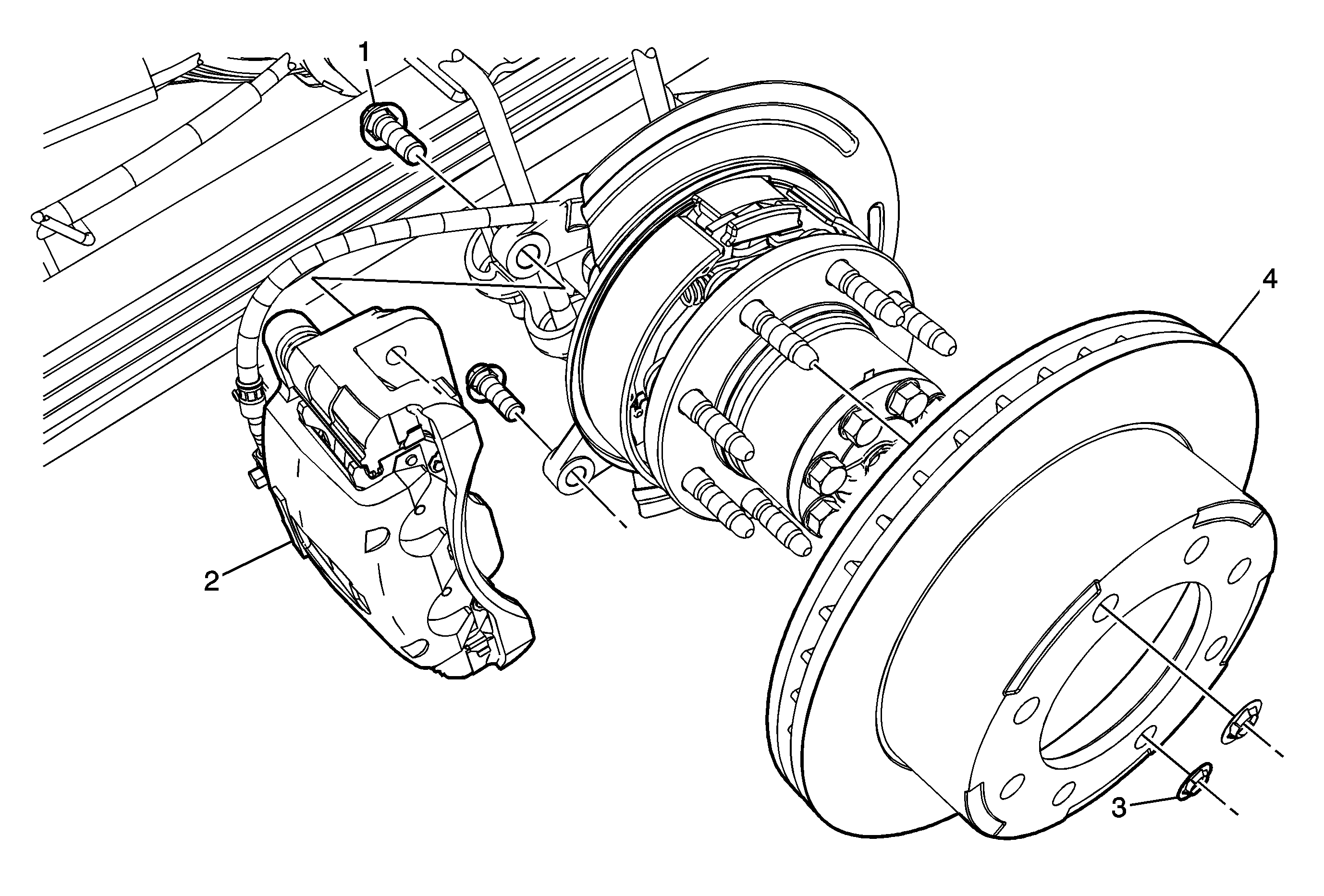
Rear Brake Rotor Replacement JH6
Callout | Component Name | ||||
|---|---|---|---|---|---|
|
Caution: Refer to Brake Dust Caution in the Preface section. Notice: Support the brake caliper with heavy mechanic wire, or equivalent, whenever it is separated from its mount and the hydraulic flexible brake hose is still connected. Failure to support the caliper in this manner will cause the flexible brake hose to bear the weight of the caliper, which may cause damage to the brake hose and in turn may cause a brake fluid leak. Notice: Any new rotor must have the protective coating removed from the friction surfaces before being placed in service. Remove the protective coating using denatured alcohol or an equivalent brake cleaner, and wipe the surface clean with clean cloths. Do not use gasoline, kerosene, or other oil base solvents which may leave an oily residue. This residue is damaging to the brake lining and is flammable. Preliminary Procedures
| |||||
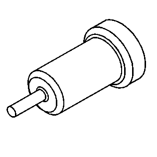
1 | Brake Caliper Bracket Bolt (Qty: 2) Notice: Refer to Fastener Notice in the Preface section. Procedure
Tighten | ||||
2 | Brake Caliper and Bracket Assembly ProcedureWithout disconnecting the brake hose from the brake caliper, remove the brake caliper and bracket as an assembly and support with heavy mechanics wire or equivalent. | ||||
3 | Brake Rotor Retainer (Qty: 2) ProcedureDiscard the brake rotor retainers. | ||||
4 | Brake Rotor Procedure
Special Tools
| ||||
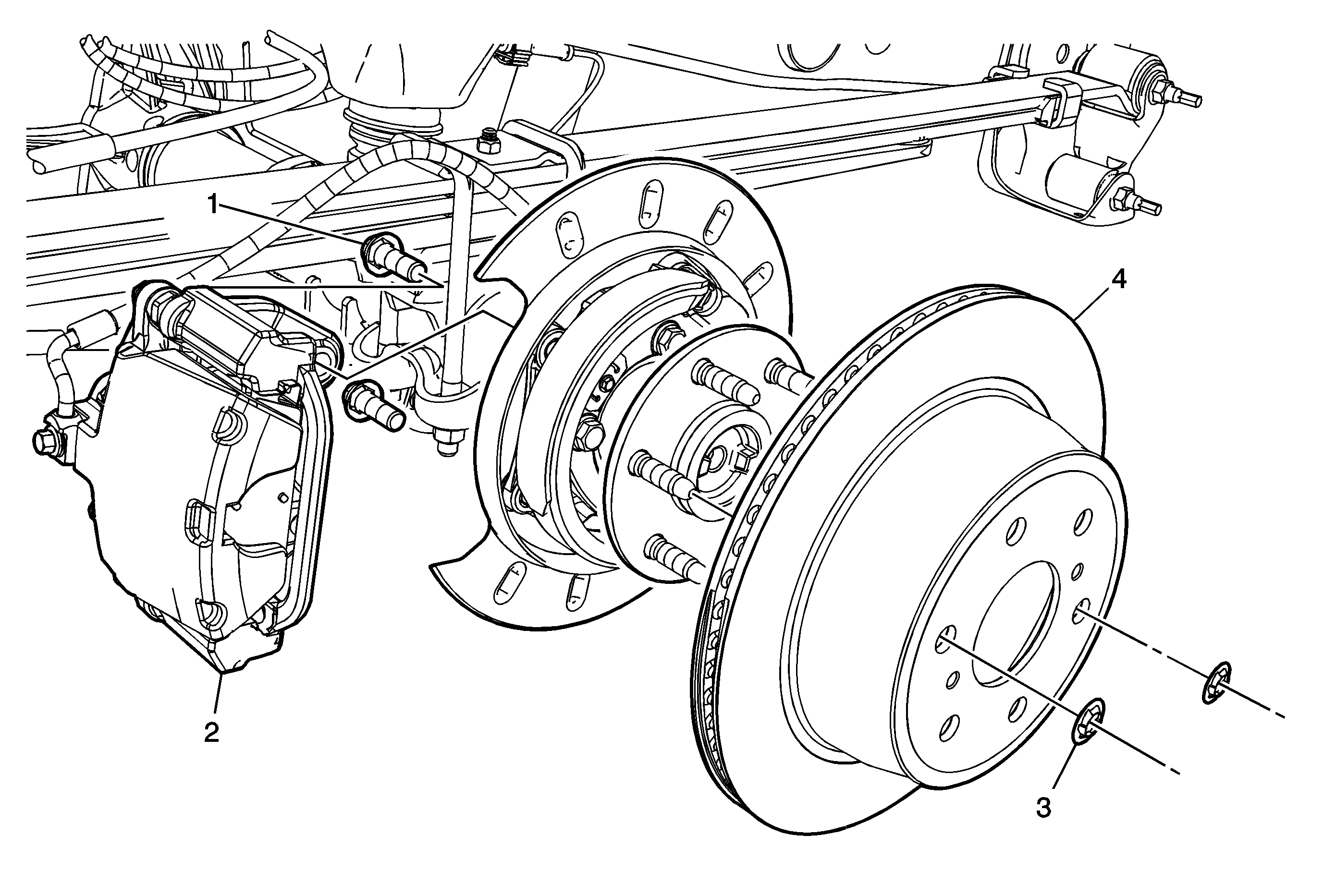
Rear Brake Rotor Replacement JD9
Callout | Component Name | ||||
|---|---|---|---|---|---|
|
Caution: Refer to Brake Dust Caution in the Preface section. Notice: Support the brake caliper with heavy mechanic wire, or equivalent, whenever it is separated from its mount and the hydraulic flexible brake hose is still connected. Failure to support the caliper in this manner will cause the flexible brake hose to bear the weight of the caliper, which may cause damage to the brake hose and in turn may cause a brake fluid leak. Notice: Any new rotor must have the protective coating removed from the friction surfaces before being placed in service. Remove the protective coating using denatured alcohol or an equivalent brake cleaner, and wipe the surface clean with clean cloths. Do not use gasoline, kerosene, or other oil base solvents which may leave an oily residue. This residue is damaging to the brake lining and is flammable. Preliminary Procedures
| |||||
1 | Brake Caliper Bracket Bolt (Qty: 2) Notice: Refer to Fastener Notice in the Preface section. Procedure
Tighten | ||||
2 | Brake Caliper and Bracket Assembly ProcedureWithout disconnecting the brake hose from the brake caliper, remove the brake caliper and bracket as an assembly and support with heavy mechanics wire or equivalent. | ||||
3 | Brake Rotor Retainer (Qty: 2) | ||||
4 | Brake Rotor Procedure
Special Tools
| ||||
Rear Brake Rotor Replacement JH7
Caution: Refer to Brake Dust Caution in the Preface section.
Notice: Any new rotor must have the protective coating removed from the friction surfaces before being placed in service. Remove the protective coating using denatured alcohol or an equivalent brake cleaner, and wipe the surface clean with clean cloths. Do not use gasoline, kerosene, or other oil base solvents which may leave an oily residue. This residue is damaging to the brake lining and is flammable.
Removal Procedure
- Release the park brake.
- Raise and support the vehicle. Refer to Lifting and Jacking the Vehicle.
- Remove the tire and wheel assembly. Refer to Tire and Wheel Removal and Installation.
- Remove the hub and rotor assembly. Refer to Rear Axle Hub, Bearing, Cup, and/or Seal Replacement.
- Mark the relationship of the hub to the rotor.
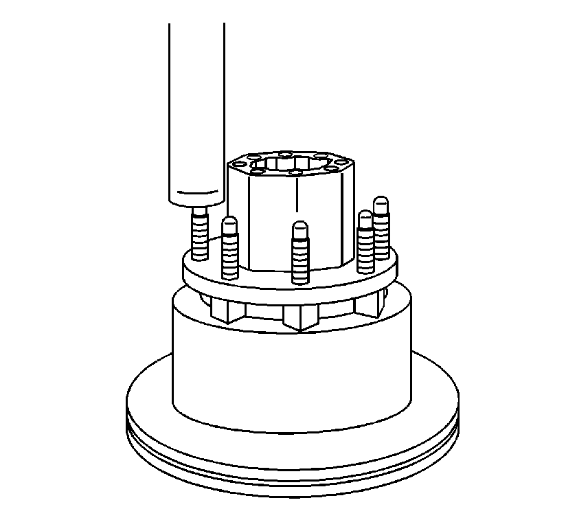
- Place the hub and rotor assembly on a hydraulic press.
- Press the wheel studs out of the hub and rotor assembly.
- Separate the hub from the rotor.
Installation Procedure
- Align the hub and the rotor.
- Install each of the new wheel studs into the hub and rotor assembly by performing the following:
- Install the hub and rotor assembly to the vehicle. Refer to Rear Axle Hub, Bearing, Cup, and/or Seal Replacement.
- Install the tire and wheel assembly. Refer to Tire and Wheel Removal and Installation.
- Lower the vehicle.
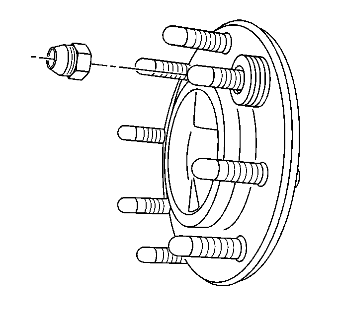
| 2.1. | Install the stud. |
| 2.2. | Install 4 washers to the stud. |
| 2.3. | Install a lug nut to the stud with the flat side of the nut toward the washers. |
| 2.4. | Tighten the lug nut to draw the stud into the hub and rotor assembly. |
| 2.5. | Inspect the hub and rotor assembly to ensure the stud is seated completely. |
| 2.6. | Remove the lug nut and the washers. |
