- Loosen the fuel fill cap to relieve vapor pressure in the fuel tank.
- Relieve the fuel system pressure.
- Remove the positive crankcase ventilation (PCV) clean air tube from air inlet duct and set aside.
- Remove the resonator and air inlet duct from throttle body.
- Remove the brake booster vacuum hose and connector from intake manifold.
- Remove the electrical connector from the central sequential fuel injection (CSFI) fuel metering body.
- Remove the spark plug wires from 1, 3 and 5 from the distributor cap.
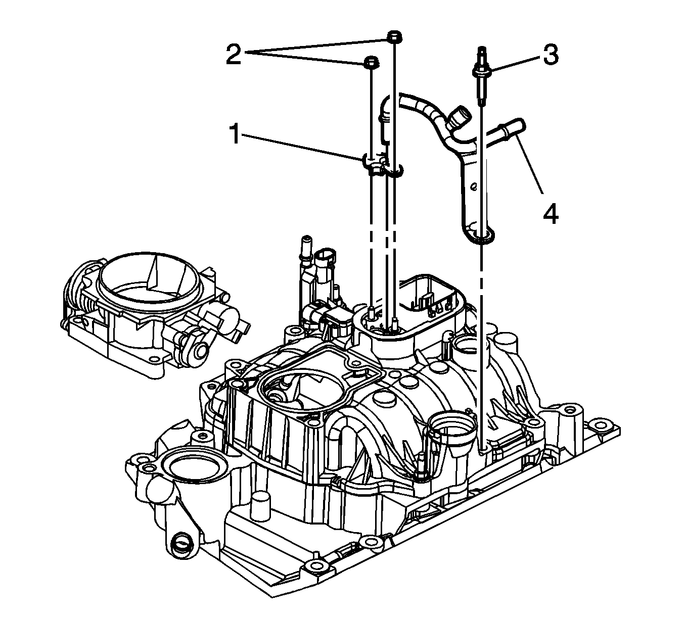
- Remove the fuel feed pipe bracket stud (3).
- Remove the fuel pipe retainer nuts (2) and retainer (1).
- Remove fuel feed pipe (4).
Important: Make sure that the fuel pipe O-rings, washers, and spacers are present and in their proper position.
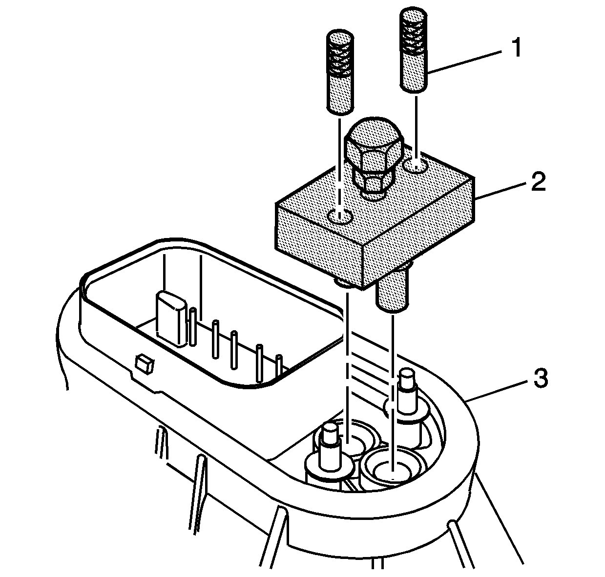
- Install the
J 44466-12
(2) and the
J 44466-13
(1) to the metering body and tighten.
- Install the
J 44466-11
, retainer, and
J 44466-13
to the fuel feed pipe and tighten.
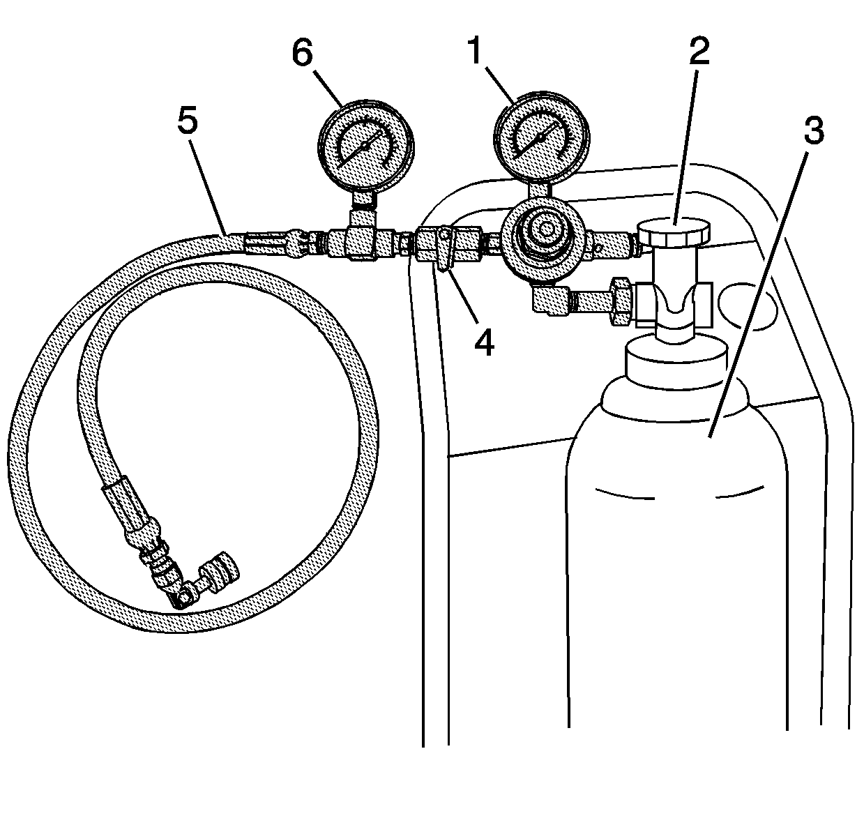
- Obtain the
J 41413
, close
the valve (2) on the tank (3), and remove the regulator assembly.
- Install the
J 44466-10
(5) to the
J 41413
tank (3)
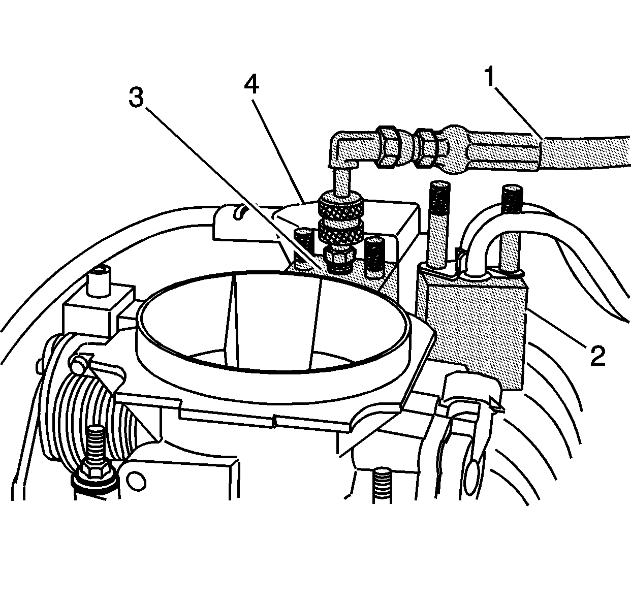
- Connect the
J 44466-10
hose (1) to the
J 44466-12
(3).
- Install the
J 39021
, the
J 39021-210
and
J 39021-301
(4) to the metering body electrical
connector.
- Adjust the amperage selector switch on
J 39021
to 0.5 amps.

- Open the valve (2) on the tank (3).
- Open the valve (4) on the
J 44466-10
to pressurize the fuel system. Then close valve (4) before firing injectors.
Important: The minimum pressure required on the gage (6) is 150 psi. If 150 psi is not obtained, the tank (3) must be refilled prior to performing this procedure.
- Fire one injector using the
J 39021
. Observe a pressure drop on the gage (6) and verify the injector/poppet valve operation. An injector/poppet that is stuck and not operational will have no pressure
drop on the gage. If an injector remains stuck, repeat the procedure multiple times (as required) until the injector is operational.
- Repeat steps 19 and 20 for each individual injector to verify that all injector/poppet valve assemblies are unstuck and functional.
- Shut off the pressure valve (2) on the tank (3) of the
J 41413
.
- Bleed off the pressure at the
J 44466-10
.
- Install the PCV fresh air tube to the air inlet duct.

- Disconnect and remove the
J 44466-10
(1) from the
J 44466-12
(3) and the
J 41413
.
- Remove the
J 39021-301
,
J 39021-210
and
J 39021
from the metering body.
- Install the vehicle electrical connector to the metering body.
- Install brake booster vacuum hose and connector to the intake manifold.
- Install ignition wires 1, 3, and 5 to the distributor cap.
- Install the resonator and air intake duct to the throttle body and hand tighten wing nut.
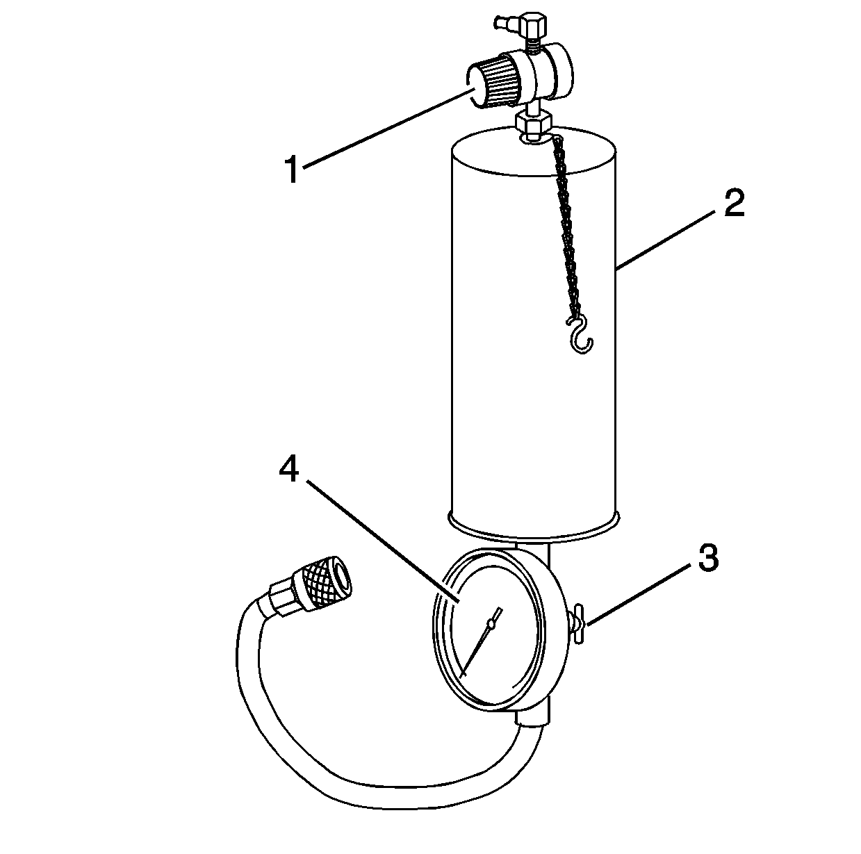
- Obtain
J 38500-A
(2).
Important: Make sure the valve at the bottom of the canister (3) is closed.
- Remove the canister top and add top engine cleaner GM P/N 1050002 (Canadian P/N 992872) to the canister.
- Fill the remainder of the canister with regular unleaded gasoline and install the canister top.
- Suspend
J 38500-A
from a convenient underhood location.

- Connect the hose from
J 38500-A
(1) to the service port on the
J 44466-12
(3).

- Open valve (3) at the bottom of
J 38500-A
.
- Connect a shop air source to the fitting at the top of
J 38500-A
and adjust the regulator (1) to 75 psi.
- Let the vehicle run at idle until the canister is empty and the vehicle stalls.
- Remove the shop air supply from
J 38500-A
.
- Depressurize the
J 38500-A
.
- Disconnect the
J 38500-A
hose from the
J 44466-12
.
- Remove the PCV clean air tube from the air inlet duct and set aside.
- Remove the resonator and air inlet duct from the throttle body and set aside.
- Remove ignition wires 1, 3, and 5 from the distributor cap.
- Remove brake booster vacuum hose and connector from the intake manifold.
- Bleed the residual pressure from
J 44466-12
.

- Remove
J 44466-13
(1) and
J 44466-12
(2) from
the metering body.
- Remove
J 44466-13
, retainer, and
J 44466-11
from the fuel feed pipe.
Important: Make sure that all of the O-rings (6 and 8), washers (7), and spacers (5) are present and in proper position.
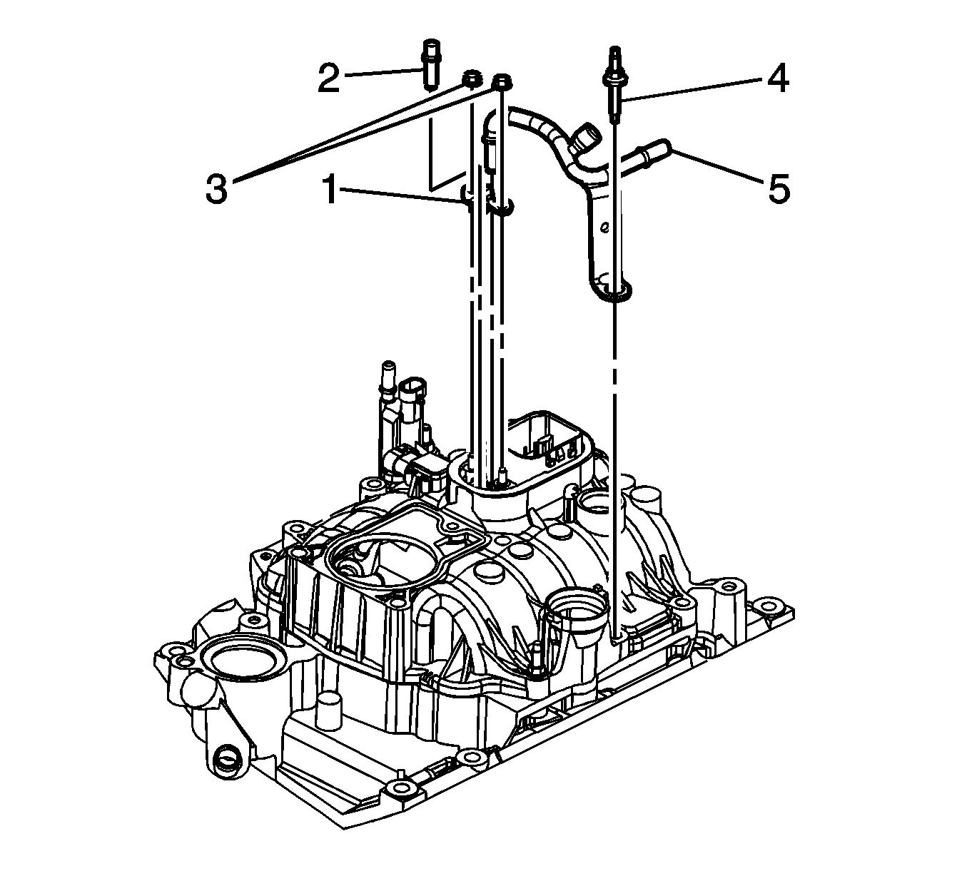
- Install the fuel feed pipe (4) to the metering body.
Notice: Use the correct fastener in the correct location. Replacement fasteners
must be the correct part number for that application. Fasteners requiring
replacement or fasteners requiring the use of thread locking compound or sealant
are identified in the service procedure. Do not use paints, lubricants, or
corrosion inhibitors on fasteners or fastener joint surfaces unless specified.
These coatings affect fastener torque and joint clamping force and may damage
the fastener. Use the correct tightening sequence and specifications when
installing fasteners in order to avoid damage to parts and systems.
- Install the retainer (1) and retainer nuts (2).
Tighten
Tighten the nuts to 3 N·m (27 lb ft).
- Apply threadlock GM P/N 12345382 (Canadian P/N 10953489) or equivalent, to the threads of the fuel feed pipe bracket stud (3).
- Install the fuel feed pipe bracket stud (3).
Tighten
Tighten the stud to 6 N·m (53 lb ft).
- Install the brake booster vacuum hose and connector to the intake manifold.
- Install the resonator and air inlet duct to the throttle body.
- Install the PCV clean air tube to the inlet duct.
- Install brake booster vacuum hose and connector to the intake manifold.
- Install ignition wires 1, 3, and 5 to the distributor cap.
- Add 1 ounce of port fuel injector cleaner GM P/N 12345104 (Canadian P/N 12345515), or equivalent to the vehicle fuel tank for each gallon of gasoline estimated to be in the tank.
Important: Instruct the customer to add the remainder of the bottle of port fuel injector cleaner to the vehicle fuel tank at the next fill up.
- Hand tighten the fuel tank filler cap.
- Start the vehicle and check for fuel leaks.
- Using a Tech II scan tool, check for any stored Powertrain DTC codes. Clear codes as required.
- Disconnect Tech II scan tool.


