For 1990-2009 cars only
Tools Required
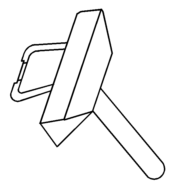
J 37228 Seal Cutter
Removal Procedure
- Disconnect the negative battery cable. Refer to Battery Negative Cable Disconnection and Connection .
- Remove the water pump. Refer to Water Pump Replacement .
- Remove the crankshaft front oil seal. Refer to Crankshaft Front Oil Seal Replacement .
- Remove the right wheelhouse panel. Refer to Front Wheelhouse Liner Replacement - Right Side .
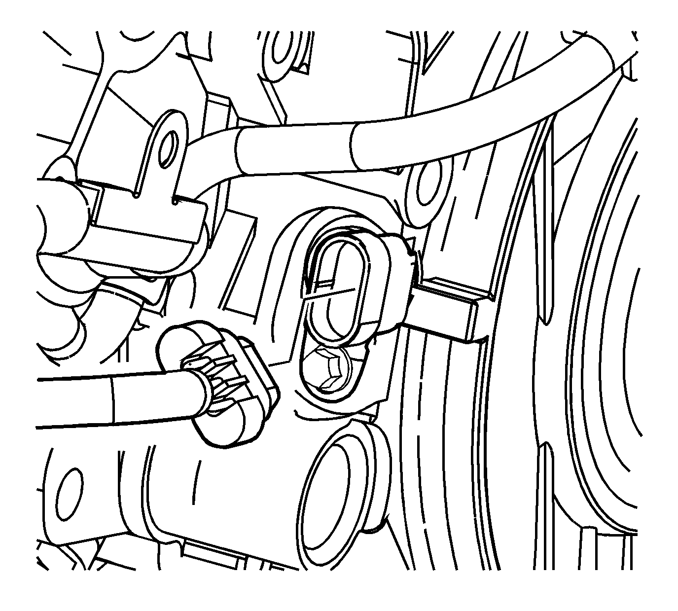
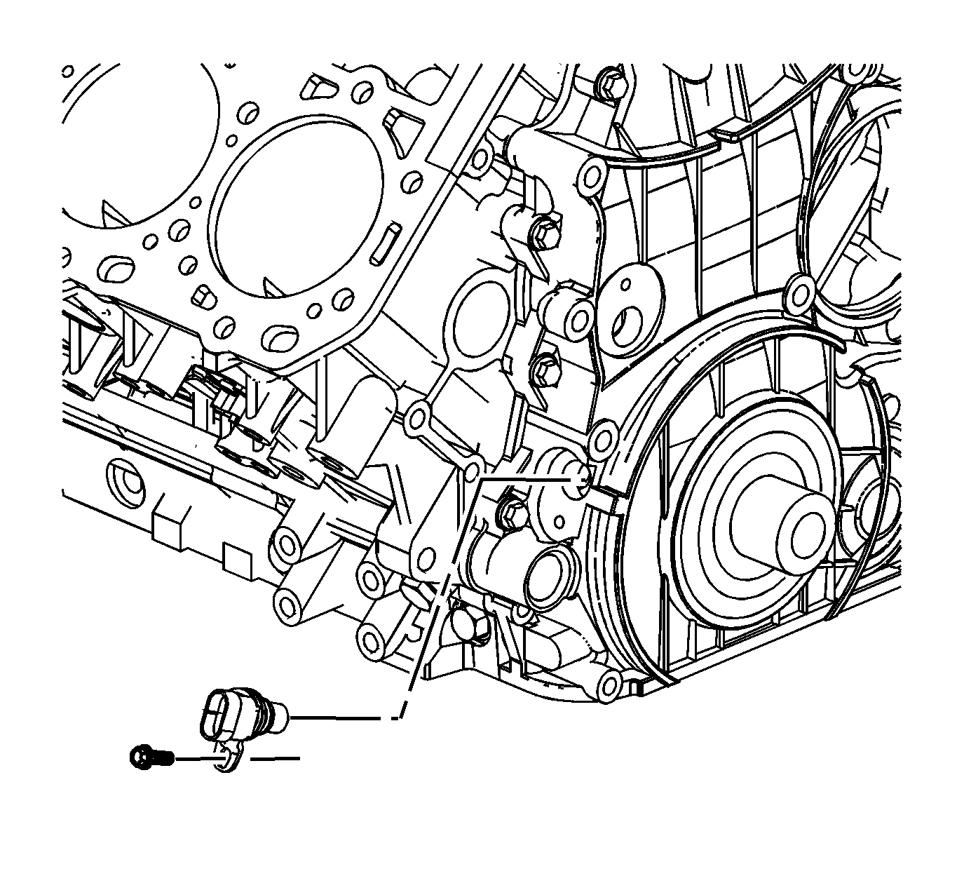
- Disconnect the crankshaft position (CKP) sensor electrical connector.
- Remove the CKP sensor bolt and sensor.
- Remove the CKP sensor spacer bolts and spacer.
- Remove and discard the O-rings from the sensor and the spacer.
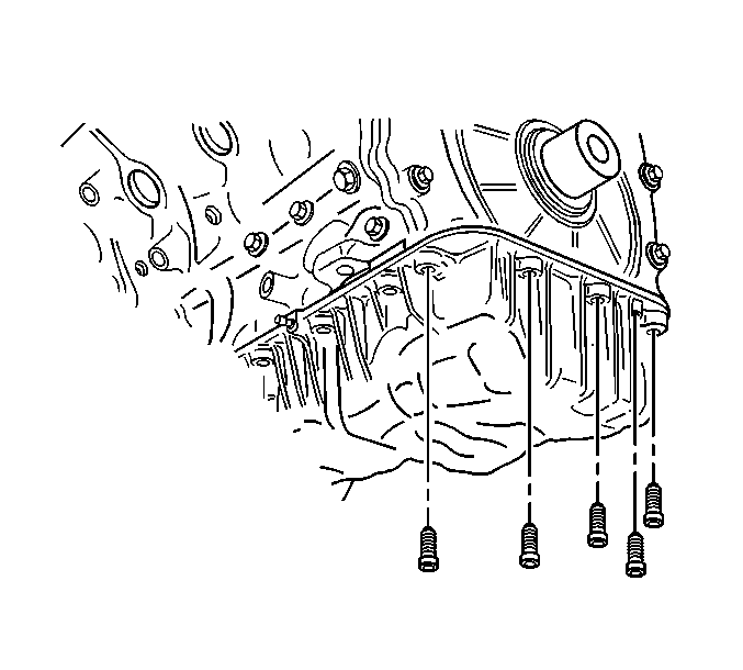
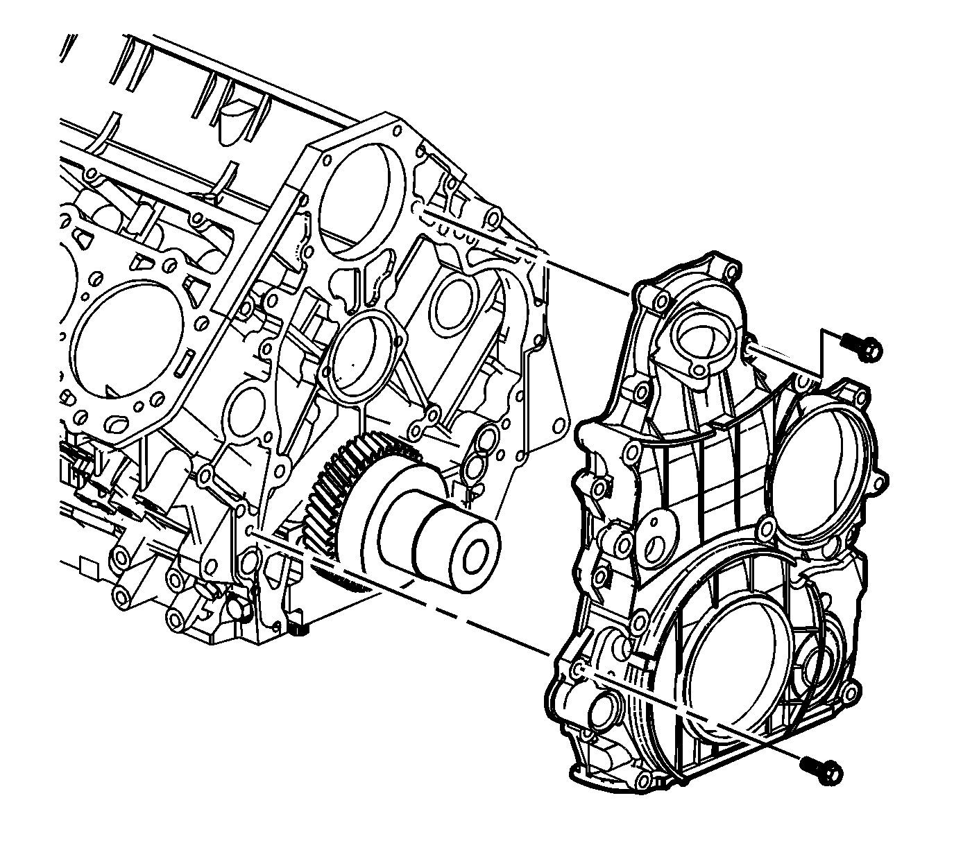
- Remove the upper oil pan to engine front cover bolts.
- Remove the engine front cover bolts.
- Separate the engine front cover from the cylinder block and upper oil pan using J 37228 .
- Remove the engine front cover.
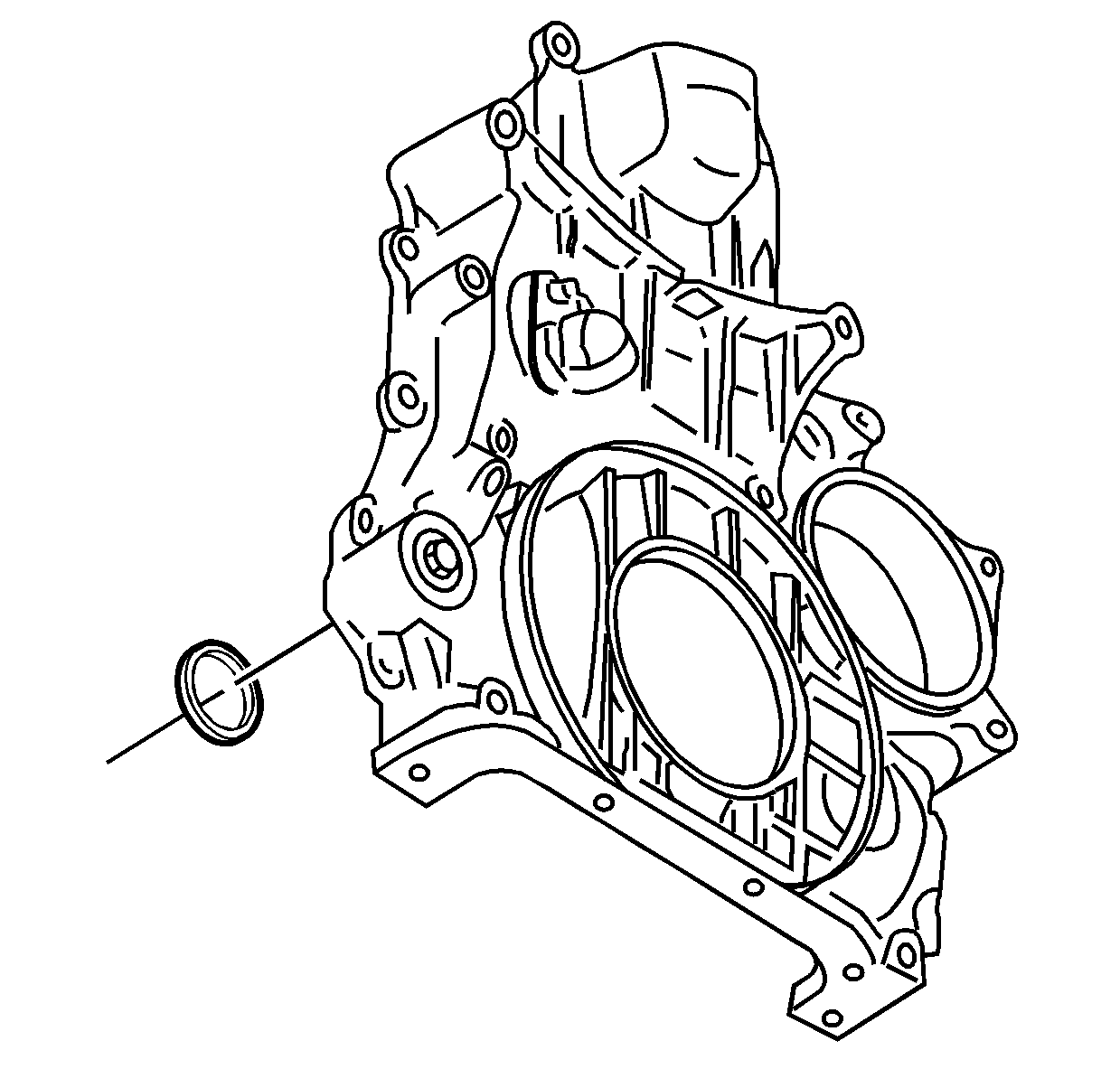
- If necessary, remove the pressure relief valve O-ring.
- Clean and inspect the front cover. Refer to Engine Front Cover Cleaning and Inspection .
Important: Do not bend the turbocharger coolant pipe.
Installation Procedure
- If necessary, install a NEW pressure relief valve O-ring.
- Lubricate the O-ring with engine oil.
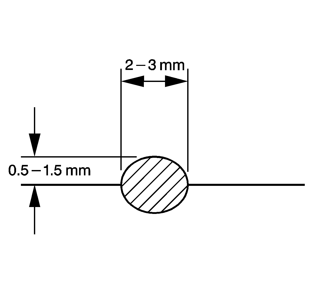
- Apply a 2-3 mm (1/8 in) wide by 0.5-1.5 mm (1/16 in) high, bead of sealant to the engine front cover sealing surface to the engine block. Refer to Adhesives, Fluids, Lubricants, and Sealers for the correct part number.
- Apply a 2-3 mm (1/8 in) wide by 0.5-1.5 mm (1/16 in) high, bead of sealant to the engine front cover sealing surface to the upper oil pan. Refer to Adhesives, Fluids, Lubricants, and Sealers for the correct part number.
- Install the engine front cover.
- Install the engine front cover bolts.
- Install the upper oil pan to engine front cover bolts.
- Install a NEW O-ring to the CKP sensor spacer.
- Lubricate the O-ring with clean engine oil.
- Install the CKP sensor spacer and bolts.
- Install a NEW O-ring to the CKP sensor.
- Lubricate the O-ring with clean engine oil.
- Install the CKP sensor and bolt.
- Connect the CKP sensor electrical connector.
- Install the right wheelhouse panel. Refer to Front Wheelhouse Liner Replacement - Right Side .
- Install the crankshaft front oil seal. Refer to Crankshaft Front Oil Seal Replacement .
- Install the water pump. Refer to Water Pump Replacement .
- Connect the negative battery cable. Refer to Battery Negative Cable Disconnection and Connection .
Notice: Refer to Fastener Notice in the Preface section.
Tighten
Tighten the valve to 39 N·m (29 lb ft).
Tighten
Tighten the bolts to 25 N·m (18 lb ft).
Tighten
Tighten the bolts to 21 N·m (15 lb ft).
Important: The crankshaft position sensor spacers are machined with different timing positions. However, if the crankshaft position sensor spacer requires replacement, replace with a grade "C" spacer.
Tighten
Tighten the bolts to 10 N·m (89 lb in).
Tighten
Tighten the bolt to 10 N·m (89 lb in).
