Removal Procedure
- Remove the starter motor. Refer to Starter Motor Replacement.
- If RWD vehicle, raise the vehicle to a height to work through the front wheelhouse opening. Refer to Lifting and Jacking the Vehicle .
- If 4-wheel drive (4WD) vehicle, raise the vehicle in order to remove the front tires and wheels and support with jackstands.
- Remove the right front tire and wheel, if necessary. Refer to Tire and Wheel Removal and Installation .
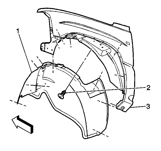
- Remove the pushpins holding the right front fender wheelhouse inner panel (1).
- Remove the wheelhouse inner panel.
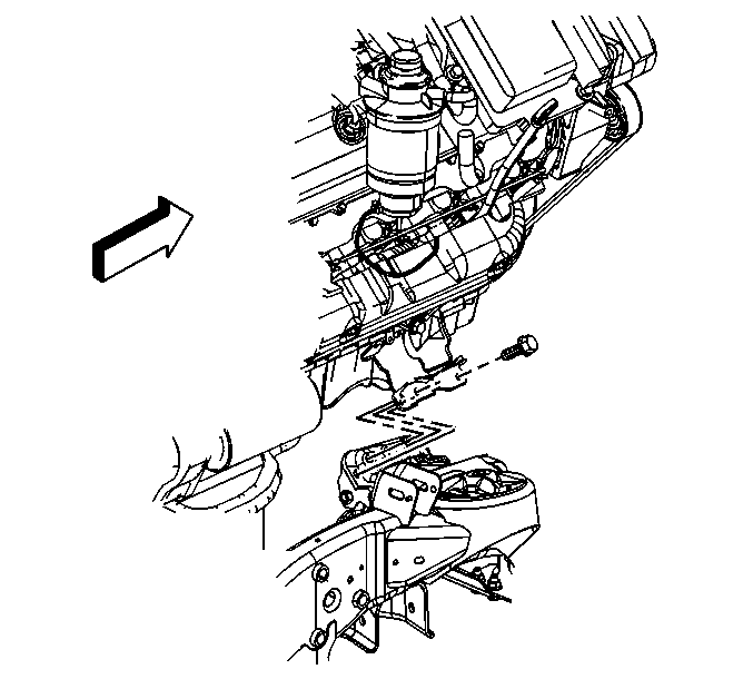
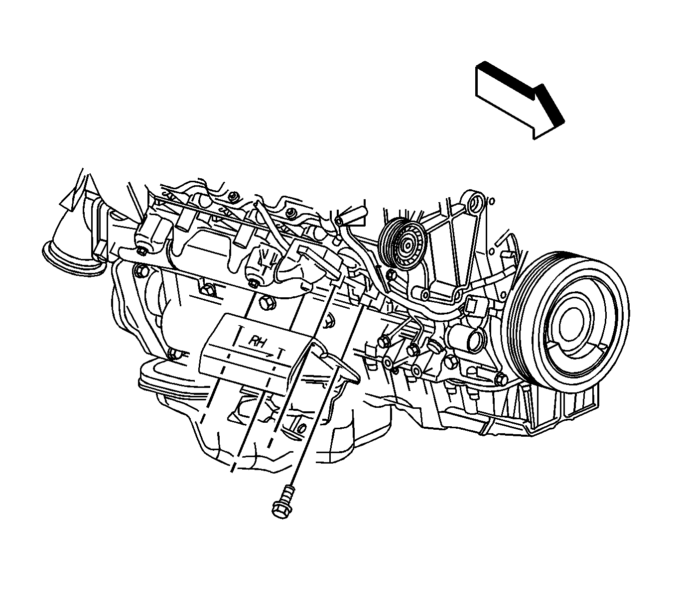
- Working through the wheelhouse opening remove the 3 bolts retaining the engine mount to the engine mount frame bracket.
- Remove the oil pan skid plate, if equipped.
- Remove the engine protection shield from the vehicle, if equipped.
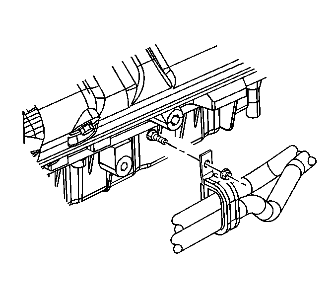
- If RWD vehicle and equipped with an automatic transmission, remove the bracket bolt for the transmission oil cooler lines to the engine.
- Move the transmission oil cooler lines aside.
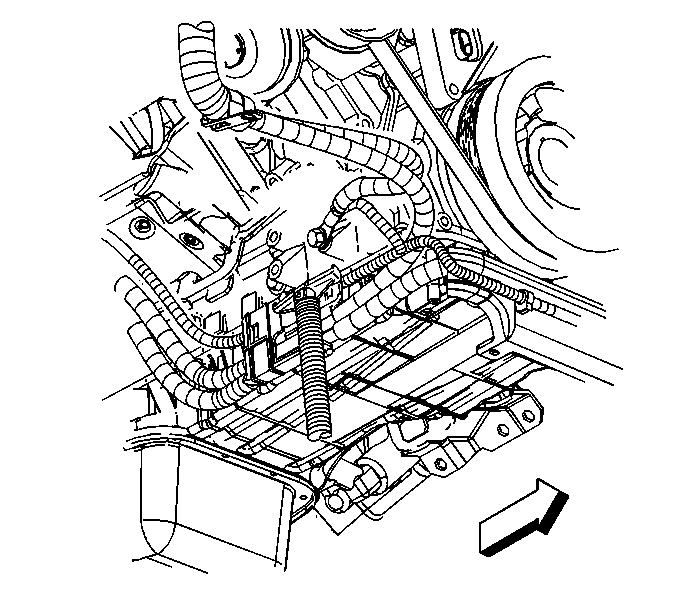
- If RWD vehicle, using a suitable jack on the ground wire bolt bosses, raise the engine.
- If 4WD vehicle, attach a chain to the front of the engine. Use accessible mounting bolts for the generator mounting bracket and the power steering pump mounting bracket.
- Raise the engine with a suitable lifting device to remove the engine mount.
- Remove the bolts holding the engine mount to the engine.
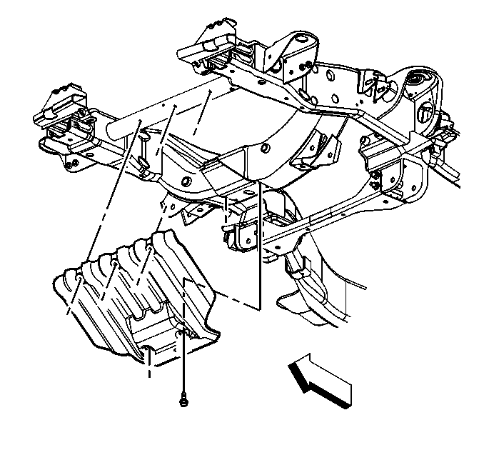
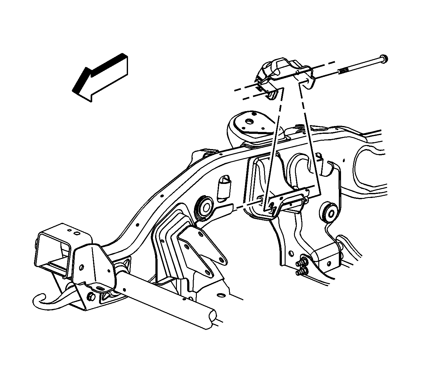
- Remove the 2 through-bolts for the engine mount frame bracket.
- Remove the engine mount frame bracket.
- Remove the engine mount.
Notice: Broken engine mountings can cause misalignment of certain drive-train components. Misalignment of drive-train components causes eventual destruction of the drive-train components.
If one engine mount breaks, the rest of the engine mounts will have increased stress put on them. This could cause the rest of the engine mounts to break.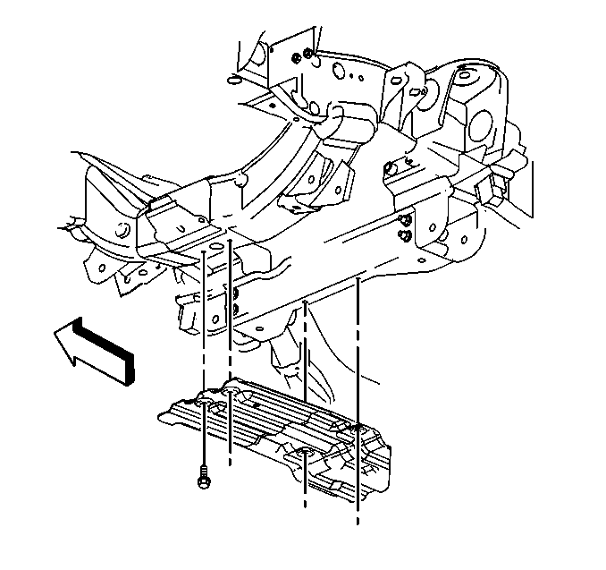
Notice: When raising or supporting the engine for any reason, do not use a jack under the oil pan, any sheet metal, or the crankshaft pulley. Lifting the engine in an unapproved manner may cause component damage.
Important: When raising the engine only raise enough to separate the engine mount from the engine mount bracket. Raising any further the fan shroud or the exhaust pipe will require removal.
Only raise the engine enough to separate the engine mount to engine mount bracket.
Only raise the engine enough to separate the engine mount to engine mount bracket.
Installation Procedure
- Position the engine mount frame bracket on the frame. Do not install the bolts.
- Install the engine mount.
- Perform the following procedure prior to installing the engine mount bracket bolts.
- Install the 2 through-bolts.
- Install the bolts holding the engine mount to the engine.
- Lower the engine.
- If 4WD vehicle, remove the chain from the front of the engine.
- If 4WD vehicle, install the generator mounting bracket and the power steering mount bracket bolt.
- Install the 3 bolts holding the engine mount to the engine mount frame bracket.
- If RWD vehicle with an automatic transmission, install the bolt for the transmission oil cooler line bracket.
- Install the engine protection shield and bolts.
- Install the oil pan skid plate.
- Install the right front tire and wheel. Refer to Tire and Wheel Removal and Installation .
- Install the front fender wheelhouse inner panel.
- Install the starter motor. Refer to Starter Motor Replacement.
- Lower the vehicle.
| 3.1. | Remove all traces of the original adhesive patch. |
| 3.2. | Clean the threads of the bolt with denatured alcohol or equivalent and allow to dry. |
| 3.3. | Apply threadlocker GM P/N 12345382 (Canadian P/N 10953489) or equivalent to the bolts. |
Notice: Refer to Fastener Notice in the Preface section.
Tighten
Tighten the through-bolts to 75 N·m (55 lb ft).
Tighten
Tighten the engine mount bolts to 58 N·m (43 lb ft).
Tighten
Tighten the mounting bracket bolts to 50 N·m (37 lb ft).
Tighten
Tighten the engine mount to engine mount frame bracket bolts to 65 N·m (48 lb ft).
Tighten
Tighten the transmission oil cooler line bracket bolt to 9 N·m (80 lb in).
Tighten
Tighten the engine protection shield bolts to 20 N·m (15 lb ft).
Tighten
Tighten the bolts to 20 N·m (15 lb ft).
