Removal Procedure
- Remove the instrument panel (I/P) upper trim panel. Refer to Instrument Panel Upper Trim Panel Replacement .
- Fully open the I/P storage compartment.
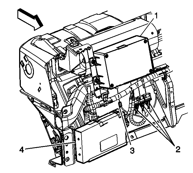
- Disconnect the electrical connectors (2) from the VCIM (1).
- Disconnect the coaxial cable (3) from the VCIM.
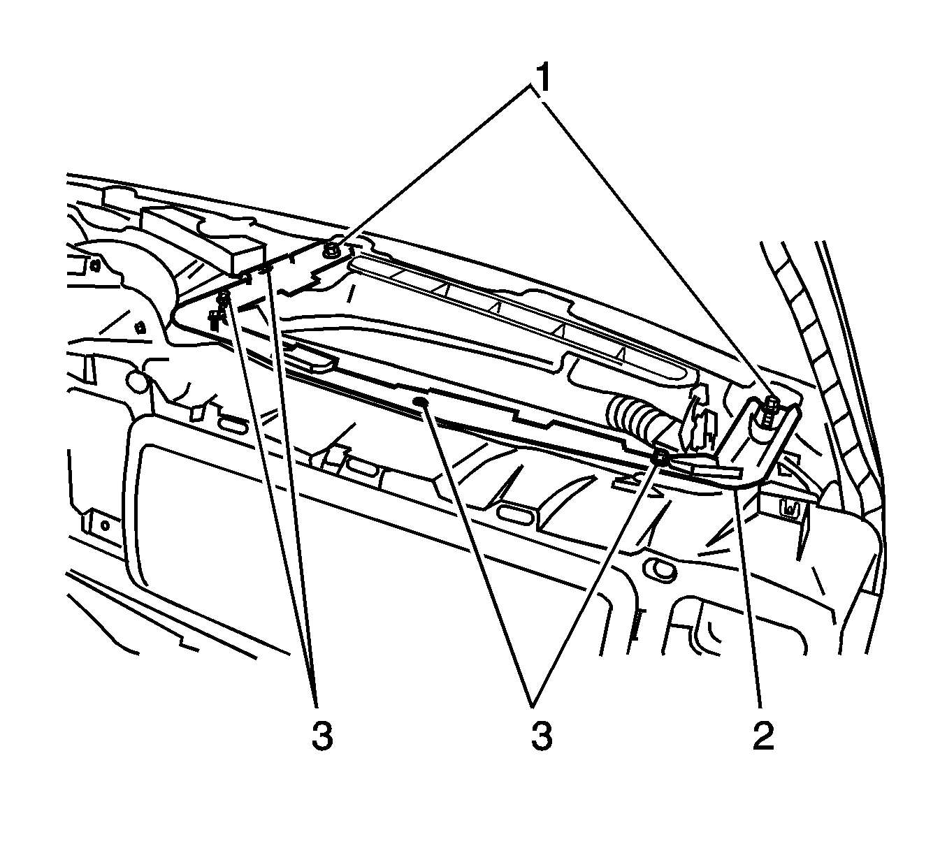
- Remove the screws (1, 3) from the passenger side upper I/P support (2).
- Remove the passenger side upper I/P support (2).
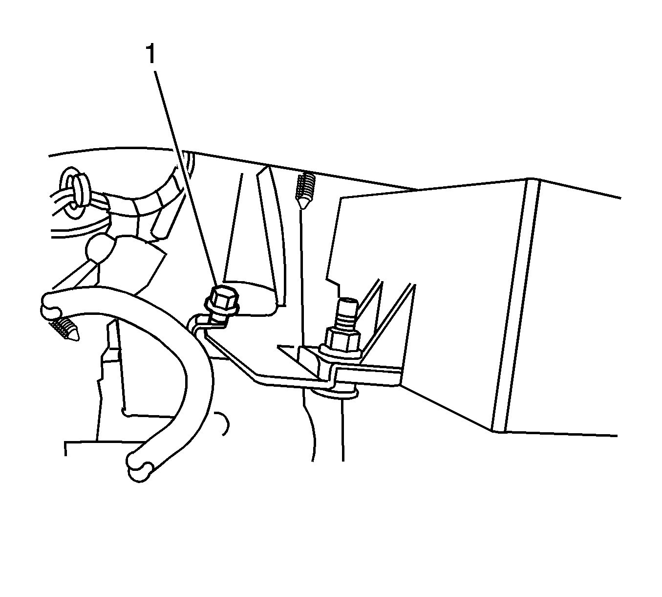
- Remove the screw (1) retaining the VCIM bracket to the I/P.
- Remove the retainer from the VCIM bracket.
- Remove the nuts holding the mounting brackets to the VCIM.
- If necessary, move the cross-car duct forward slightly in order to make room for the removal of the module.
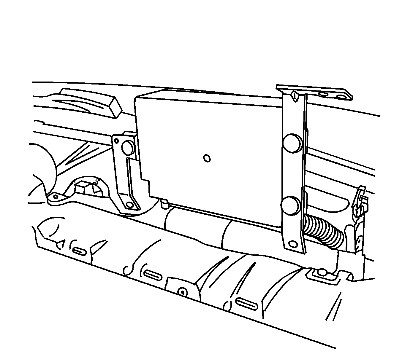
- Remove the VCIM and bracket assembly from the I/P.
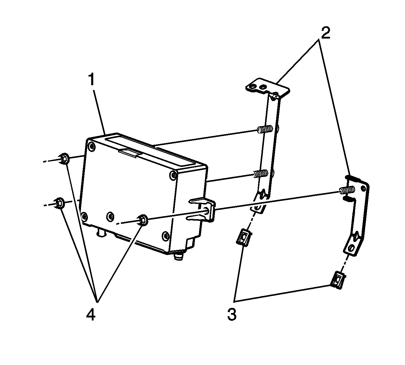
- Remove the nuts (4) from the VCIM mounting brackets (2).
- Remove the mounting brackets (2) from the VCIM (1).
Important: The vehicle communication interface module (VCIM) has a specific set of unique numbers that tie the module to each vehicle. These numbers, the 10-digit station identification and the 11-digit electronic serial number, are used by the National Cellular Network and OnStar® to identify the specific vehicle. Because these numbers are tied to the vehicle identification number of the vehicle, you must never exchange these parts with those of another vehicle.
Installation Procedure
- If replacing the VCIM, record the 10-digit STID number, and the 11-digit ESN number from the labels on the new module.
- Ensure the nuts (3) are installed on the module mounting brackets (3).
- Install the mounting brackets (2) to the VCIM (1).
- Install the nuts (4).
- If necessary, move the cross-car duct forward slightly in order to make room for the installation of the module.
- Install the VCIM and bracket assembly to the I/P.
- Install the push in retainer.
- Install the VCIM screw (1) to the I/P.
- Install the passenger side upper I/P bracket (2).
- Install the I/P upper bracket screws (3).
- Install the I/P upper bracket screws (1).
- Connect the coaxial cable (3) to the VCIM.
- Connect the electrical connectors (2) to the VCIM.
- Install the I/P trim panel. Refer to Instrument Panel Upper Trim Panel Replacement .
- Install the scan tool. Use the special functions menu in order to perform the OnStar® setup procedure for this vehicle.
- Move the vehicle to an open area that is away from tall buildings and with a clear view of unobstructed sky. Allow the vehicle to run for 10 minutes.
- Use the ID information menu on the scan tool to access the new station ID (STID) and the electronic serial number (ESN) from the new VCIM.
- Press the blue OnStar® button to connect to the OnStar® Call Center and perform the following procedure:
- The default language for voice recognition in the generation 5 OnStar® module is English. To change the language resident in the module, refer to OnStar Reconfiguration .
- Refer to Control Module References for programming and setup information.

Notice: Refer to Fastener Notice in the Preface section.
Tighten
Tighten the nuts to 2 N·m (18 lb in).


Tighten
Tighten the screws to 2 N·m (18 lb in).

Tighten
Tighten the screws (3) to 2 N·m (18 lb in).
Tighten
Tighten the screws (1) to 50 N·m (37 lb ft).

Important: After replacing the vehicle communication interface module, you must reconfigure the OnStar® system. Failure to reconfigure the system will result in an additional customer visit for repair. In addition, pressing and holding the white dot button on the keypad will NOT reset this version of the OnStar® system. This action will cause a DTC to set.
| 18.1. | Tell the advisor that this vehicle has received a new VCIM. |
| 18.2. | Ask the advisor to add the new STID and the ESN to update the customer's account. |
| 18.3. | Follow any additional instructions from the OnStar® advisor. |
| 18.4. | Ask the advisor to activate the OnStar® Personal Calling feature, if available. |
