Removal Procedure
- Raise and support the vehicle. Refer to Lifting and Jacking the Vehicle.
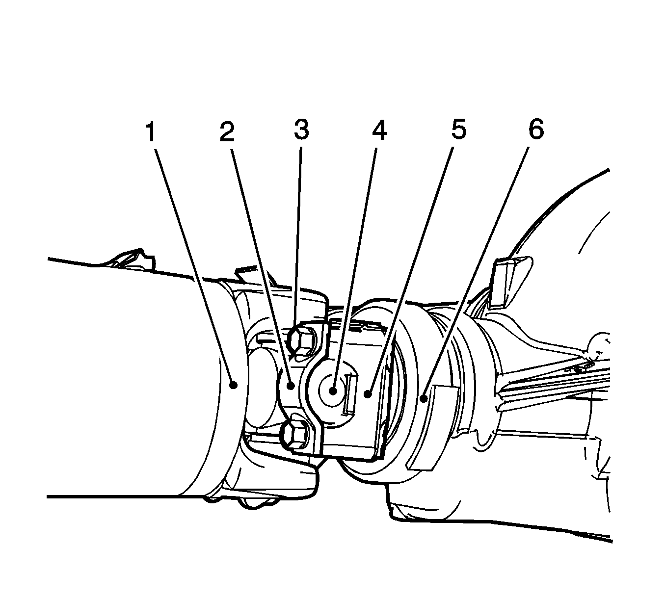
- Reference mark the propeller shaft (1), the universal joint strap (2), universal bearing cap (4), the drive pinion yoke (5), and the rear axle housing (6).
- Remove the bolts (3) and the universal straps (2) from the rear axle pinion yoke (5).
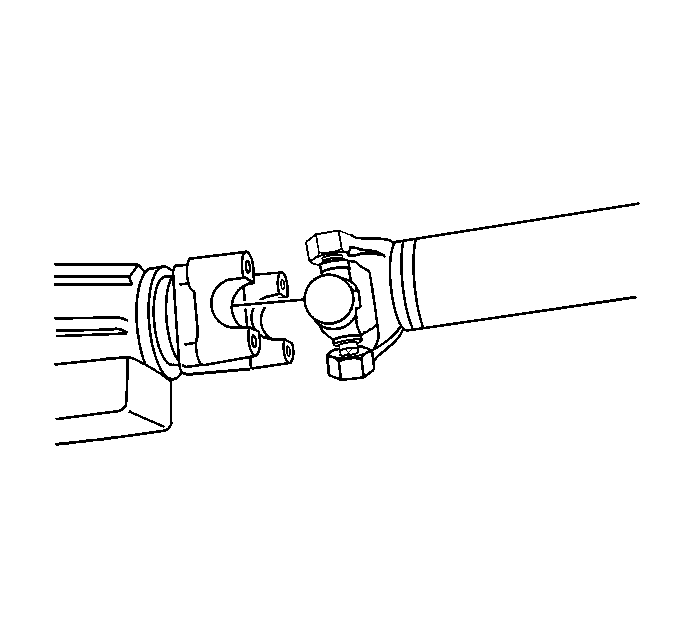
- Remove the propeller shaft from the rear axle pinion yoke.
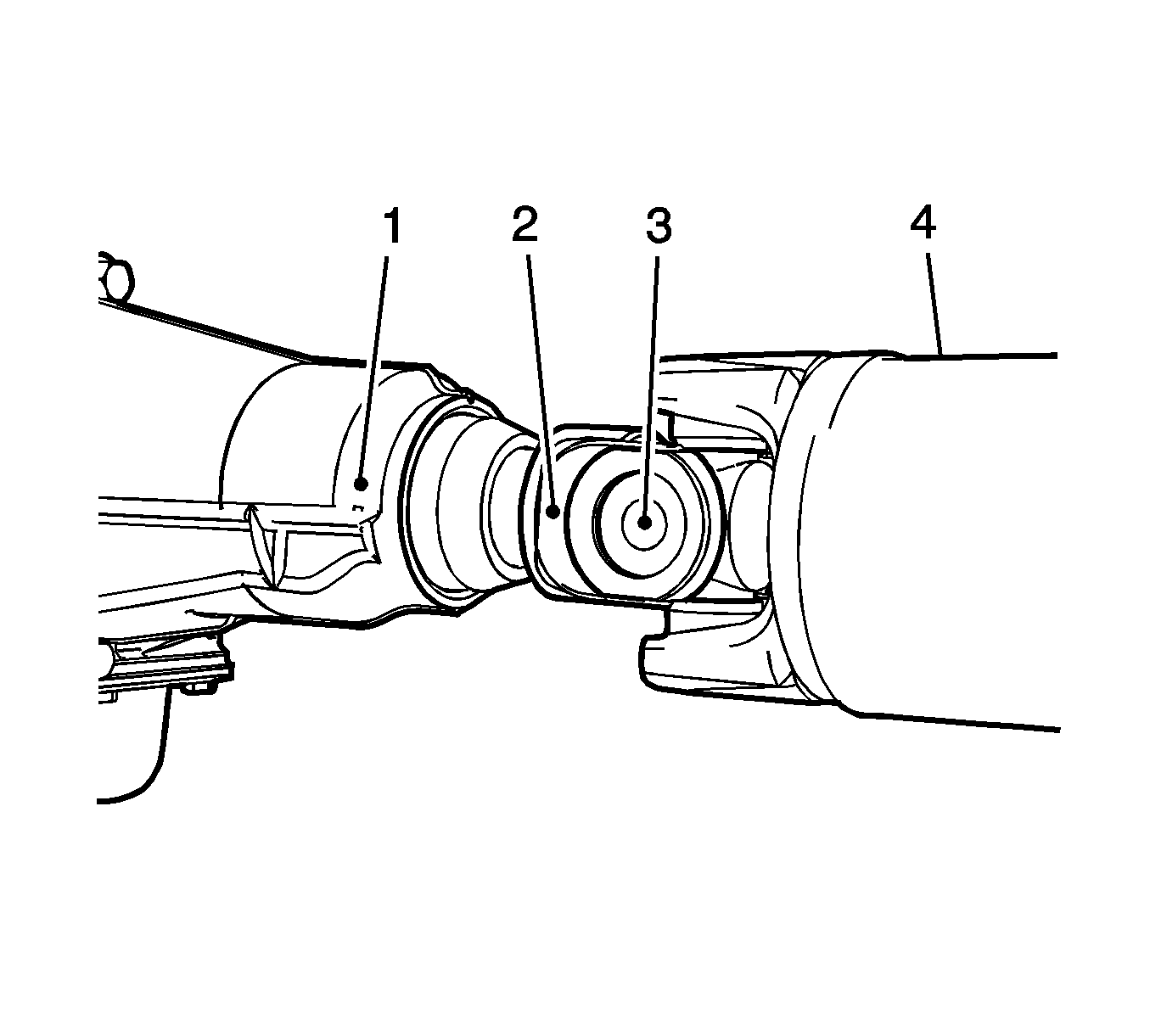
- Reference mark the transmission or the transfer case (1), propeller shaft flip yoke (2), universal joint bearing cap (3), and the propeller shaft (4).
- Remove the propeller shaft from the vehicle.
Important: Observe and accurately reference mark all driveline components relative to the propeller shaft and axles before disassembly. These components include the propeller shafts, the drive axles, the pinion flanges, the output shafts, etc. All components must be reassembled in the exact relationship to each other as they were when removed. In addition, published specifications and torque values, as well as any measurements made prior to disassembly must be followed.

Notice: When removing the propeller shaft, do not attempt to remove the shaft by pounding on the yoke ears or using a tool between the yoke and the universal joint. If the propeller shaft is removed by using such means, the injection joints may fracture and lead to premature failure of the joint.


Installation Procedure
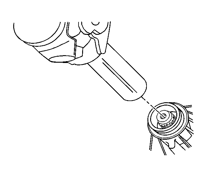
- Inspect the splines of the slip yoke for a sufficient coating of grease. If the splines of the slip yoke does not have a sufficient coating of grease, lubricate the shaft with clean grease or transmission fluid.
- Align the reference marks on the propeller shaft (4), the slip yoke (2), the universal bearing caps (3), the transmission or the transfer case (1).
- Install the propeller shaft in the transmission or transfer the case.
- Align the reference marks on the propeller shaft (1), universal bearing cap (4), pinion flange (5), and the rear axle housing (6).
- With the reference marks aligned, install the propeller shaft (1) on the rear axle (6).
- Install the rear propeller shaft bolts (3) and the strap (2).
- Remove the support and lower the vehicle.


Important: Ensure that the reference marks are aligned before installing the propeller shaft.
Notice: Refer to Fastener Notice in the Preface section.
Tighten
Tighten the yoke retainer bolts to 25 N·m (18 lb ft).
