Rear Disc Brake Pads Replacement With Single Rear Wheel
Removal Procedure
Warning: Refer to Brake Dust Warning in the Preface section.
Caution: Refer to Brake Fluid Effects on Paint and Electrical Components Caution in the Preface section.
- Inspect the fluid level in the brake master cylinder reservoir.
- If the brake fluid level is midway between the maximum-full point and the minimum allowable level, no brake fluid needs to be removed from the reservoir before proceeding.
- If the brake fluid level is higher than midway between the maximum-full point and the minimum allowable level, remove brake fluid to the midway point before proceeding.
- Raise and suitably support the vehicle. Refer to Lifting and Jacking the Vehicle.
- Remove the tire and wheel assembly. Refer to Tire and Wheel Removal and Installation.
- Inspect the caliper operation. Refer to Brake Caliper Inspection.
- Place a C-clamp as shown. Slowly bottom the pistons of the caliper. It may be necessary to reposition the C-clamp to allow both of the pistons to bottom into the caliper bores.
- Remove the caliper from the mounting bracket and support the caliper with heavy mechanic's wire or equivalent. DO NOT disconnect the hydraulic brake flexible hose from the caliper. Refer to Rear Brake Caliper Replacement.
- Inspect the caliper assembly. Refer to Brake Caliper Inspection.
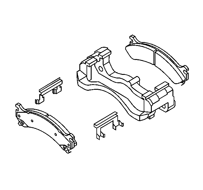
- Remove the brake pads from the brake caliper bracket. Note the orientation.
- Remove and discard the anti-rattle clips from the brake caliper mounting bracket.
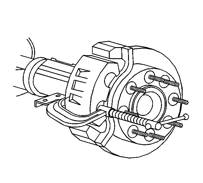
Caution: Support the brake caliper with heavy mechanic wire, or equivalent, whenever it is separated from its mount and the hydraulic flexible brake hose is still connected. Failure to support the caliper in this manner will cause the flexible brake hose to bear the weight of the caliper, which may cause damage to the brake hose and in turn may cause a brake fluid leak.
Installation Procedure
- Install the anti-rattle clips to the brake caliper bracket.
- Install the brake caliper. Refer to Rear Brake Caliper Replacement.
- Install the brake pads to the brake caliper bracket. Place the new pads in the same orientation as noted during removal.
- Install the tire and wheel assembly. Refer to Tire and Wheel Removal and Installation.
- Lower the vehicle.
- With the engine OFF, gradually apply the brake pedal to approximately 2/3 of its travel distance.
- Slowly release the brake pedal.
- Wait 15 seconds, then repeat steps 6-7 until a firm pedal is obtained. This will properly seat the brake caliper pistons and brake pads.
- Fill the master cylinder reservoir to the proper level with clean brake fluid. Refer to Master Cylinder Reservoir Filling.
- Burnish the brakes pads and rotors as necessary. Refer to Brake Pad and Rotor Burnishing.

Rear Disc Brake Pads Replacement With Dual Rear Wheel
Removal Procedure
Warning: Refer to Brake Dust Warning in the Preface section.
- Inspect the fluid level in the brake master cylinder reservoir.
- If the brake fluid level is midway between the maximum-full point and the minimum allowable level, no brake fluid needs to be removed from the reservoir before proceeding.
- If the brake fluid level is higher than midway between the maximum-full point and the minimum allowable level, remove brake fluid to the midway point before proceeding.
- Raise and support the vehicle. Refer to Lifting and Jacking the Vehicle.
- Remove the tire and wheel assembly. Refer to Tire and Wheel Removal and Installation.
- Position a large C-clamp against the outboard disc brake pad backing plate and over the rear of the brake caliper body.
- Using the C-clamp, slowly and evenly bottom the brake caliper pistons into the brake caliper bores.
- Remove the brake caliper bracket bolts (1).
- Remove the brake caliper and bracket assembly (1) and support with heavy mechanics wire or equivalent.
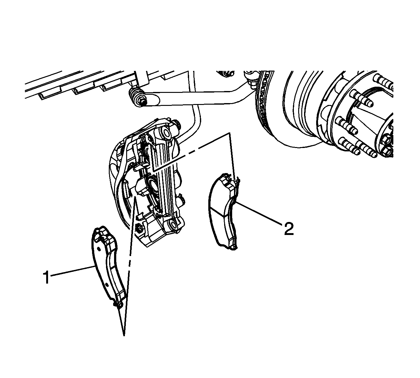
- Remove the outer brake pad (1).
- Remove the inner brake pad (2).
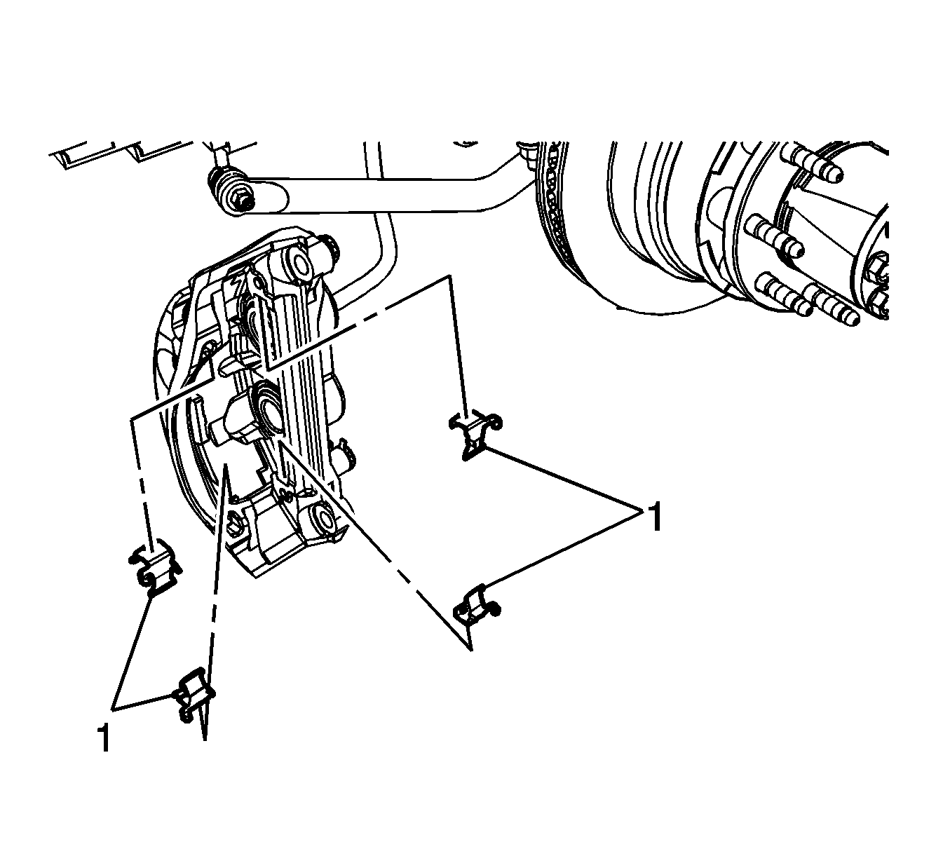
- Remove the brake pad springs (1).
- Clean the brake pad springs contact areas of the brake caliper bracket of any accumulated corrosion and debris.
Note: Do not remove the brake caliper guide pins unless replacement is required.
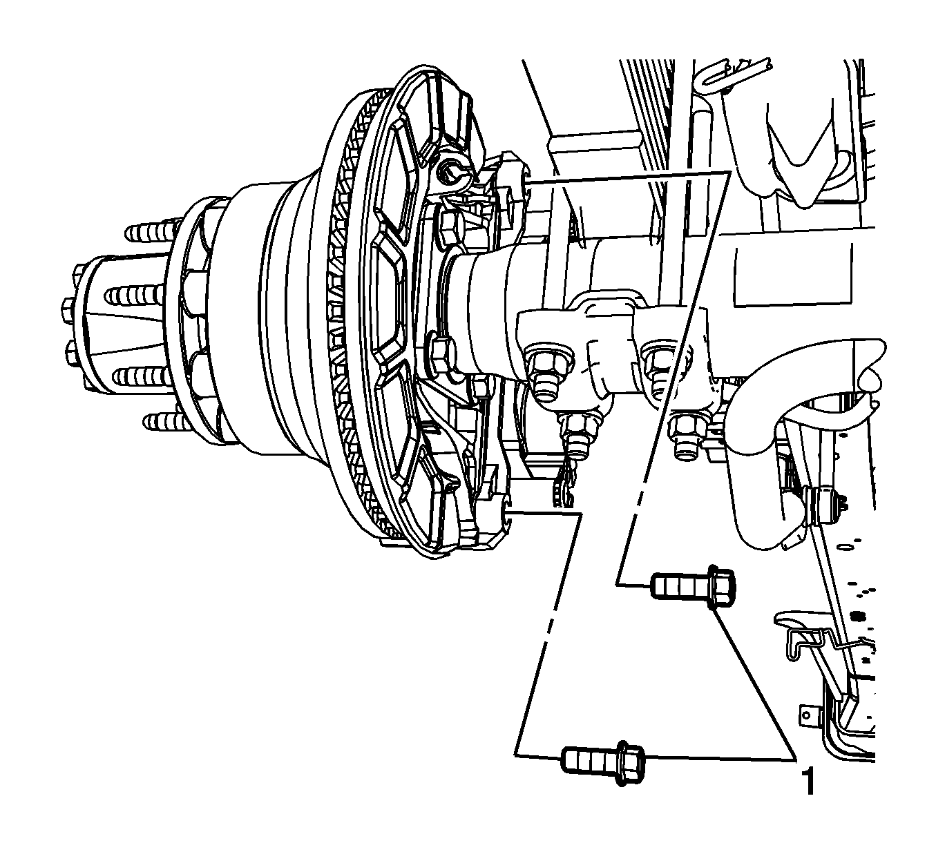
Caution: Support the brake caliper with heavy mechanic wire, or equivalent, whenever it is separated from its mount and the hydraulic flexible brake hose is still connected. Failure to support the caliper in this manner will cause the flexible brake hose to bear the weight of the caliper, which may cause damage to the brake hose and in turn may cause a brake fluid leak.
Installation Procedure
- Ensure the brake caliper guide pin caps (1) are in good condition and firmly seated on the brake caliper body.
- Without disengaging the brake caliper from the brake caliper guide pins, inspect the brake caliper hardware. Refer to Rear Disc Brake Mounting and Hardware Inspection.
- Install the brake pad springs (1).
- Install the outer brake pad (1).
- Install the inner brake pad (2).
- Prepare the brake caliper bracket bolts and the rear axle threaded holes for assembly.
- Apply threadlocker GM P/N 89021297 (Canadian P/N 10953488) to 2/3 of the threaded length of the brake caliper bracket bolt.
- Allow the threadlocker to cure approximately 10 minutes before assembly.
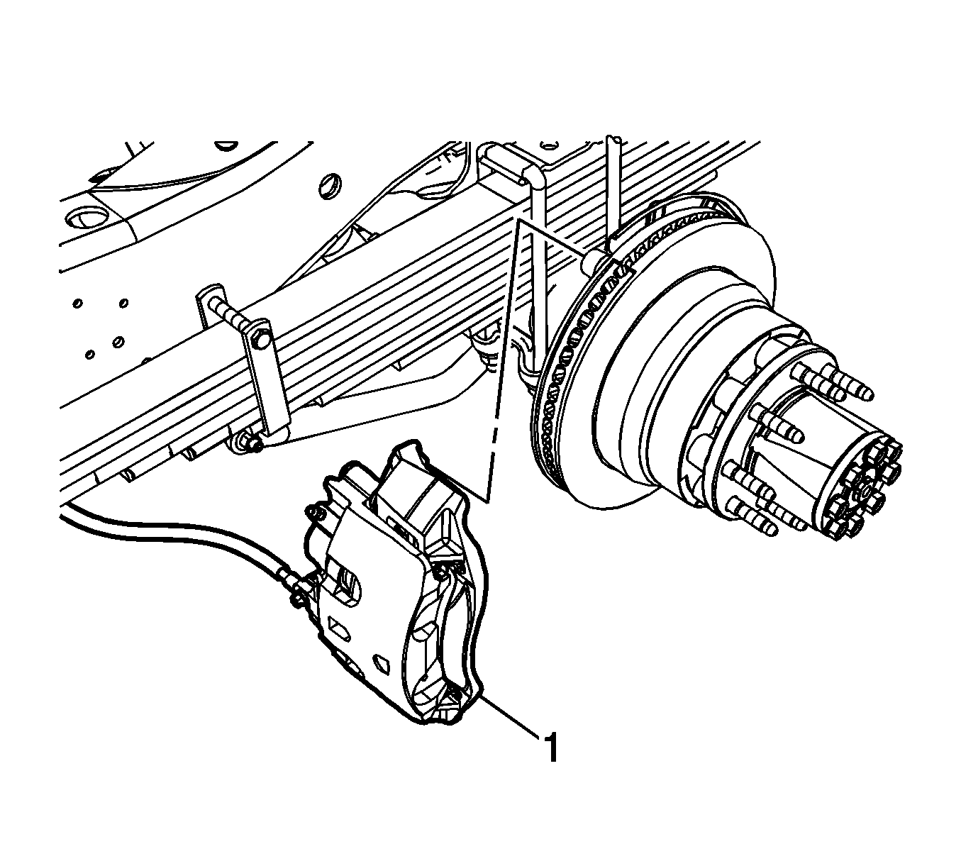
- Position the brake caliper and bracket assembly (1) to the rear axle.
- Install the brake caliper bracket bolts (1) and tighten to 300N·m (221 lb ft).
- Install the tire and wheel assembly. Refer to Tire and Wheel Removal and Installation.
- With the engine OFF, gradually apply the brake pedal to approximately 2/3 of its travel distance.
- Slowly release the brake pedal.
- Wait 15 seconds, then repeat steps 14-15 until a firm pedal is obtained. This will properly seat the brake caliper pistons and brake pads.
- Fill the brake master cylinder. Refer to Master Cylinder Reservoir Filling.
- Burnish the brake pads and rotors. Refer to Brake Pad and Rotor Burnishing.
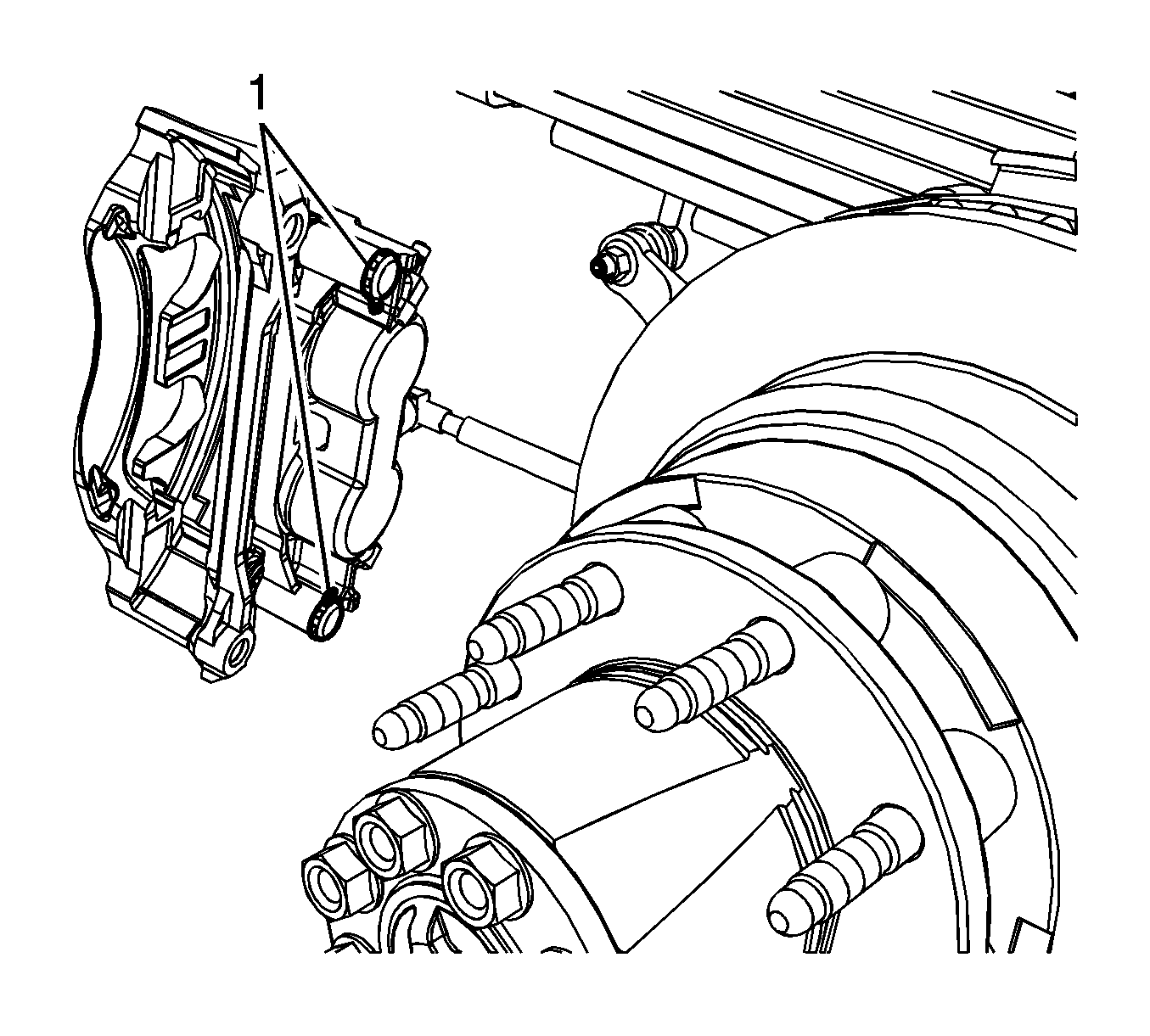
Replace any missing or damaged brake caliper guide pin caps.


| • | Clean the brake caliper bracket bolts of any threadlocking residue |
| • | Clean the rear axle threaded holes of any threadlocking residue with denatured alcohol and allow to dry |

Caution: Refer to Fastener Caution in the Preface section.

