1-2 and 2-3 Shift Solenoid Valves

The 1-2 and 2-3 shift solenoid valves (also called A and B solenoids) are identical devices that control the movement of the 1-2 and 2-3 shift valves. The 3-4 shift valve is not directly controlled by a shift solenoid. The solenoids are normally-open exhaust valves that work in 4 combinations to shift the transmission into different gears.
The powertrain control module (PCM) or transmission control module (TCM) energizes each solenoid by grounding the solenoid through an internal quad driver. This sends current through the coil winding in the solenoid and moves the internal plunger out of the exhaust position. When ON, the solenoid redirects fluid to move a shift valve.
Important: The manual valve hydraulically can override the shift solenoids. Only in D4 do the shift solenoid states totally determine what gear the transmission is in. In the other manual valve positions, the transmission shifts hydraulically and the shift solenoid states CATCH UP when the throttle position and the vehicle speed fall into the correct ranges.
The PCM/TCM-controlled shift solenoids eliminate the need for TV and governor pressures to control shift valve operation.
Transmission Pressure Control Solenoid
The transmission pressure control solenoid is an electronic pressure regulator that controls pressure based on the current flow through its coil winding. The magnetic field produced by the coil moves the solenoid's internal valve which varies pressure to the pressure regulator valve.
The powertrain control module (PCM) or transmission control module (TCM) controls the pressure control solenoid by commanding current between 0.1-1.1 amps. This changes the duty cycle of the solenoid, which can range between 5-95 percent, typically less than 60 percent. High amperage (1.1 amps) corresponds to minimum line pressure, and low amperage (0.1 amp) corresponds to maximum line pressure, if the solenoid loses power, the transmission defaults to maximum line pressure.
The PCM/TCM commands the line pressure values, using inputs such as engine speed and throttle position sensor voltage.
The pressure control solenoid takes the place of the throttle valve or the vacuum modulator that was used on past model transmissions.
Torque Converter Clutch Solenoid Valve

The torque converter clutch (TCC) solenoid valve is a normally-open exhaust valve that is used to control torque converter clutch apply and release. When grounded, energized, by the powertrain control module (PCM) or transmission control module (TCM), the TCC solenoid valve stops converter signal oil from exhausting. This causes converter signal oil pressure to increase and move the TCC solenoid valve into the apply position.
Torque Converter Clutch Pulse Width Modulation Solenoid Valve
The torque converter clutch pulse width modulation solenoid valve controls the fluid acting on the converter clutch valve. The converter clutch valve controls the torque converter clutch (TCC) apply and release. This solenoid is attached to the control valve body assembly within the transmission. The TCC PWM solenoid valve provides a smooth engagement of the torque converter clutch by operating during a duty cycle percent of ON time.
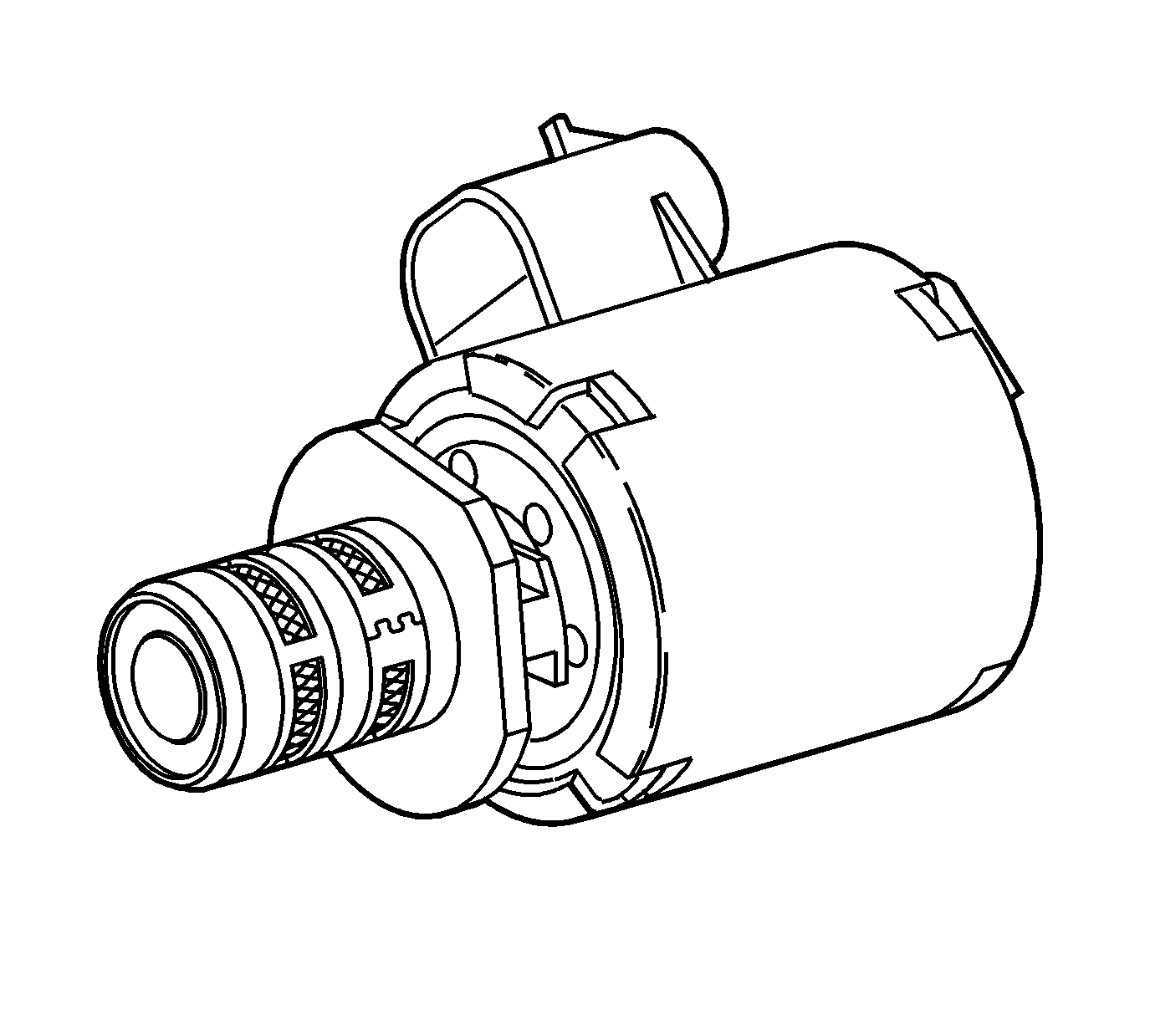
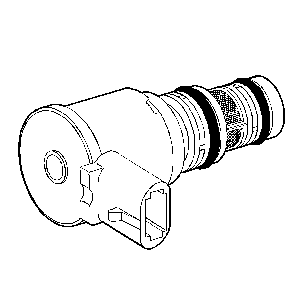
Vehicle Speed Sensor Assembly
The vehicle speed sensor (VSS) provides vehicle speed information to the powertrain control module (PCM) or transmission control module (TCM). The VSS is a permanent magnet (PM) generator. The PM generator produces a pulsing AC voltage as rotor teeth on the transmission output shaft pass through the sensor's magnetic field. The AC voltage level and the number of pulses increase as the speed of the vehicle increases. Output voltage varies with speed from a minimum of 0.5 volts at 100 RPM to more than 100 volts at 8,000 RPM. The PCM/TCM converts the pulsing voltage to vehicle speed. The PCM/TCM uses the vehicle speed signal to determine shift timing and TCC scheduling.
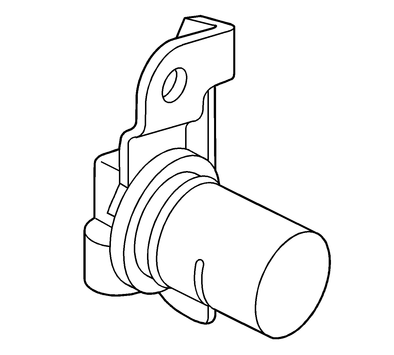
Automatic Transmission Fluid Temperature Sensor
The automatic transmission fluid temperature (TFT) sensor is part of the automatic transmission manual shift shaft position switch. The TFT sensor is a resistor, or thermistor, which changes value based on temperature. The sensor has a negative-temperature coefficient. This means that as the temperature increases, the resistance decreases and as the temperature decreases, the resistance increases.
The powertrain control module (PCM) or transmission control module (TCM) supplies a 5-volt reference signal to the TFT sensor and measures the voltage drop in the circuit. When the transmission fluid is cold, the sensor resistance is high and the PCM/TCM detects high signal voltage. As the fluid temperature warms to a normal operating temperature, the resistance becomes less and the signal voltage decreases. Refer to TFT Sensor Specifications for a complete comparison of sensor resistance, temperature and signal voltage.
The PCM/TCM uses the TFT sensor information to control shift quality and TCC application.
Transmission Range Switch
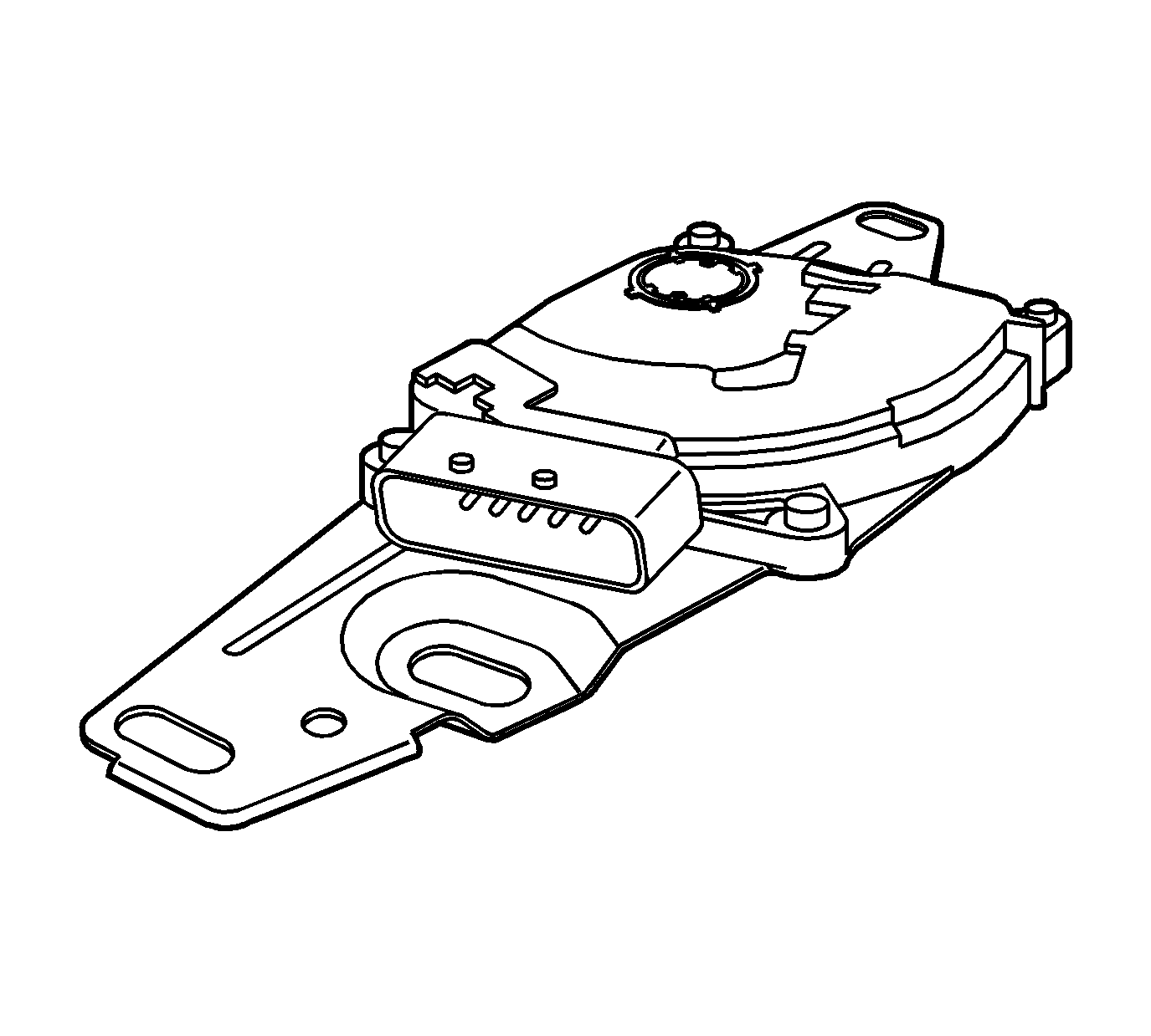
The transmission range (TR) switch is part of the park/neutral position (PNP) and backup lamp switch assembly, which is externally mounted on the transmission manual shaft. The TR switch contains four internal switches that indicate the transmission gear range selector lever position. The powertrain control module (PCM) or transmission control module (TCM) supplies ignition voltage to each switch circuit. As the gear range selector lever is moved, the state of each switch may change, causing the circuit to open or close. An open circuit or switch indicates a high voltage signal. A closed circuit or switch indicates a low voltage signal. The PCM/TCM detects the selected gear range by deciphering the combination of the voltage signals. The PCM/TCM compares the actual voltage combination of the switch signals to a TR switch combination chart stored in memory.
Tow/Haul Mode Switch

Tow/Haul mode enables the operator to achieve enhanced shift performance when towing or hauling a load. When tow/haul mode is selected, the tow/haul switch input signal to the body control module (BCM) is momentarily toggled to zero volts. This signals the powertrain control module (PCM) or transmission control module (TCM) to extend the length of time between upshifts and increase transmission line pressure. Cycling the tow/haul switch again disables tow/haul mode and returns the transmission to a normal shift pattern.
Transmission Manual Shift Shaft Switch Assembly (88)
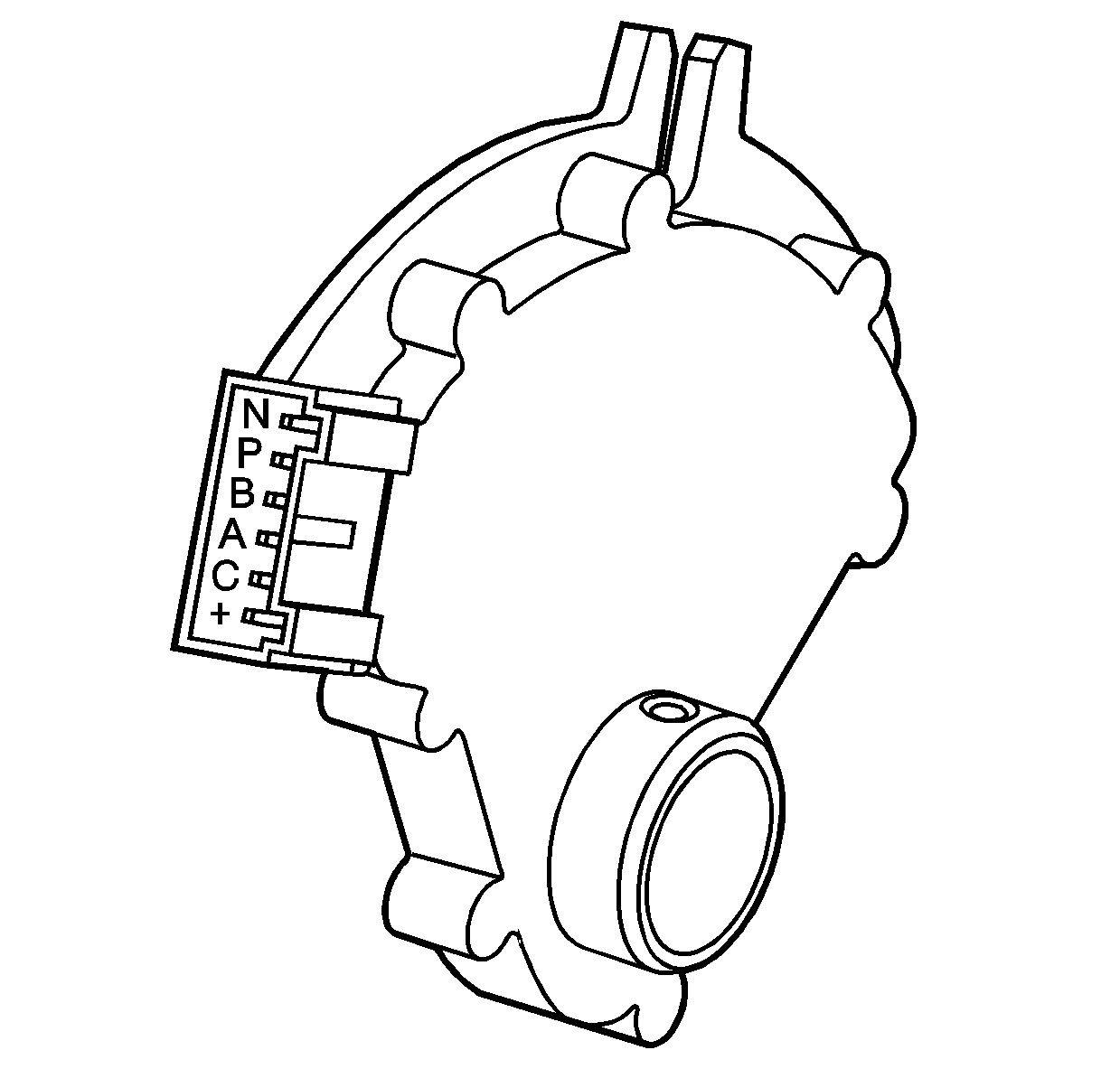
The transmission manual shift shaft switch assembly (88) is a sliding contact switch attached to the manual shift shaft inside the transmission case. The five inputs to the TCM from the transmission manual shift shaft switch assembly indicate the transmission gear selector lever position. This information is used for engine controls as well as determining the transmission shift patterns. The state of each input is available for display on the scan tool. The five input parameters represented are Signal A, Signal B, Signal C, Signal P (Parity) and Signal N (P/N Start).
