Product Safety - Hydro-Boost Accumulator Over-Pressurization

| Subject: | 05006 -- Hydro-Boost® Accumulator Over-Pressurization |
| Models: | 2004 Chevrolet Kodiak |
| 2004-2005 Chevrolet Avalanche, Express, Silverado, Suburban |
| 2004 GMC TopKick |
| 2004-2005 GMC Savana, Sierra, Yukon XL |
| 2004-2005 HUMMER H2 |
Condition
General Motors has decided that a defect, which relates to motor vehicle safety, exists in certain 2004 Chevrolet Kodiak and GMC TopKick; 2004-2005 Chevrolet Avalanche, Express, Silverado, Suburban; GMC Savana, Sierra, Yukon XL; and HUMMER H2 vehicles. On some of these vehicles, the hydraulic brake booster’s pressure accumulator may crack and/or separate from the Hydro-Boost® assembly during normal vehicle operating conditions. If a separation were to occur and the hood of the vehicle were open, fragments from the accumulator could cause injury to people in the immediate area. In addition, the presence of this crack or fractured surface could allow the hydraulic fluid to leak from the accumulator circuit of the booster assembly. The loss of fluid would cause increased steering and braking effort.
Correction
Dealers are to inspect the hydraulic brake booster, and replace it if necessary.
Vehicles Involved
Involved are certain 2004 Chevrolet Kodiak and GMC TopKick; 2004-2005 Chevrolet Avalanche, Express, Silverado, Suburban; GMC Savana, Sierra, Yukon XL; and HUMMER H2 vehicles built within these VIN breakpoints:
Year | Division | Model | From | Through |
|---|---|---|---|---|
2004 | Chevrolet | Avalanche | 4G226638 | 4G341904 |
2005 | Chevrolet | Avalanche | 5G100021 | 5G131629 |
2004 | Chevrolet | Express | 41177387 | 41248485 |
2005 | Chevrolet | Express | 51100001 | 51131250 |
2004 | Chevrolet | Kodiak | 4F512908 | 4F522809 |
2004 | Chevrolet | Silverado | 4E261349 | 4E403748 |
4F185636 | 4F269038 | |||
2005 | Chevrolet | Silverado | 5E100002 | 5E133028 |
5F800001 | 5F830223 | |||
2004 | Chevrolet | Suburban | 5G222885 | 4G340904 |
4R236779 | 4R305638 | |||
2005 | Chevrolet | Suburban | 5G100028 | 5G131914 |
5R100032 | 5R144432 | |||
2004 | GMC | Savana | 41183706 | 41907085 |
2005 | GMC | Savana | 51100003 | 51131713 |
2004 | GMC | Sierra | 4E261396 | 4E403745 |
4F193711 | 4F269043 | |||
2005 | GMC | Sierra | 5E100003 | 5E133012 |
5F800011 | 5F830202 | |||
2004 | GMC | TopKick | 4F512721 | 4F520130 |
2004 | GMC | Yukon XL | 4G223117 | 4G325593 |
4R238549 | 4R320260 | |||
2005 | GMC | Yukon XL | 5G100030 | 5G131811 |
5R100003 | 5R144343 | |||
2004 | HUMMER | H2 | 4H113129 | 4H122801 |
2005 | HUMMER | H2 | 5H100001 | 5H112855 |
Important: Dealers should confirm vehicle eligibility through GMVIS (GM Vehicle Inquiry System) before beginning recall repairs. [Not all vehicles within the above breakpoints may be involved.]
For US
For dealers with involved vehicles, a Campaign Initiation Detail Report containing the complete Vehicle Identification Number, customer name and address data has been prepared and will be loaded to the GM DealerWorld, Recall Information website. Dealers that have no involved vehicles currently assigned will not have a report available in GM DealerWorld.
For Canada
For dealers with involved vehicles, a Campaign Initiation Detail Report containing the complete Vehicle Identification Number, customer name and address data has been prepared and is being furnished to involved dealers. Dealers that have no involved vehicles currently assigned will not receive a report with the recall bulletin.
For Export
For dealers with involved vehicles, a Campaign Initiation Detail Report containing the complete Vehicle Identification Number, customer name and address data has been prepared and is being furnished to involved dealers. Dealers that have no involved vehicles currently assigned will not receive a report with the recall bulletin.
The Campaign Initiation Detail Report may contain customer names and addresses obtained from Motor Vehicle Registration Records. The use of such motor vehicle registration data for any other purpose other than follow-up necessary to complete this recall is a violation of law in several states/provinces/countries. Accordingly, you are urged to limit the use of this report to the follow-up necessary to complete this program.
Parts Information
A very small number of vehicles (less than 90 world-wide) will require the replacement of the hydraulic brake booster. Do not order boosters for shelf stock. When a replacement is required, order the appropriate booster from GMSPO. All replaced boosters (excluding Export) must be returned to the Warranty Parts Center . Hold the booster until you receive the request for return.
Special Tool
Beginning February 18, 2005, each dealer was shipped a Hydro-Boost Checking Tool, CH 47950, for use in this recall. This tool is being furnished at no charge. Additional tools, if required, may be purchased by contacting SPX Kent-Moore at 1-800-468-6657.
Service Procedure
Inspection
Tools Required
CH 47950 Hydro-Boost Checking Tool
- With the vehicle transmission in PARK or NEUTRAL, set the park brake.
- With the engine OFF, make a minimum of five (5) high effort brake applies until the pedal feels hard.
- Start the engine.
- Turn the steering wheel to the "steering lock" (fully turned) position. Hold at the steering lock position for 1 to 2 seconds and then release the steering wheel. Repeat a total of 3 times.
- Turn the vehicle off, being careful not to step on the brake pedal.
- For Express/Savana only:
- Using a clean, lint-free shop cloth, wipe any dirt away from the steering pump supply hose/tube connection area on the hydro-boost (this is the center hose/tube of the three).
- Disconnect the power steering supply hose/tube from the hydro-boost unit and wrap a clean lint-free shop cloth around the end of the hose and secure it in the engine compartment.
- Using a clean lint-free shop cloth, clean any dirt off of the inlet port adapter valve assembly. Before installing the inlet port adapter, place a shop cloth below the booster supply port in order to capture any fluid exiting the hydro-boost unit.
- Install the inlet port adapter, CH 47950-2 (2) into the booster supply port.
- Using a torque wrench, slowly tighten the inlet port adapter to 16 N·m(12 lb ft). If the clear tube was removed from the inlet port adapter assembly, be sure it is re-installed
- Before each use of the accumulator pressure clamp, CH 47950-1, be sure to grease the clamp bolt and anti rotation washer with wheel bearing grease
- Install the accumulator pressure clamp, CH 47950-1 (1), by sliding it over the accumulator and straddling the hydro-boost housing.
- Confirm that the accumulator pressure clamp is squarely seated onto the booster housing and accumulator, and place the ¾ inch containment bolt into the fixture. Install the nut hand-tight onto the containment bolt.
- Check and make sure that the fixture washer is correctly positioned between the end of the accumulator, and that the pin is engaged in the end of the bolt. The tab on the washer should be rotated clockwise so it is located below the master cylinder mounting flange ear.
- Hand-tighten the accumulator pressure clamp bolt. Make sure the clamp is level and the tube is square to the end of the accumulator.
- Place a shop cloth next to the opening of the inlet port adapter in order to capture any fluid exiting the hydro-boost unit.
- Slowly tighten the fixture clamp bolt while monitoring the inlet port adapter tube for signs of power steering fluid.
- Loosen the clamp bolt, remove the clamp containment bolt, and remove the accumulator pressure clamp. Remove the inlet port adapter from the supply port of the booster. Wipe the excess power steering fluid off of the adapter with a clean, lint-free shop cloth. Store the adapter in a clean location, such as a plastic bag.
- Reinstall the supply hose/tube to the booster.
- Clean any spilled fluid from the outside of the booster.
- For Express/Savana only:
- Start the engine and run at idle. Depress the brake pedal 5 times. Turn the steering wheel to the "steering lock" position. Hold for 1-2 seconds. Check to see if there is any leakage from the ports/fittings.
- Turn the engine off.
- If leaks were observed, re-check that the fittings are at the recommended torque values. Repeat Steps 17 and 18.
- Check the power steering reservoir fluid level, add fluid if necessary.
- Close the hood.
Important: DO NOT depress the brake pedal until instructed.
| 6.1. | Remove the remote power steering reservoir mounting nuts. |
| 6.2. | Disconnect the reservoir outlet hose from the booster unit. Keeping the hose end higher than the reservoir, reposition the reservoir forward and down out of the way. |
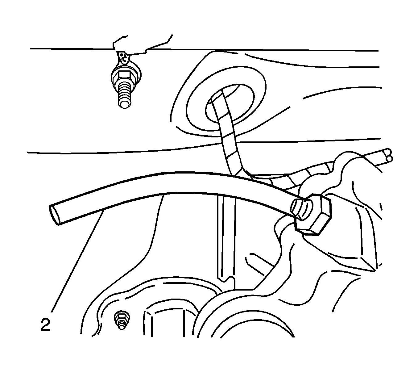
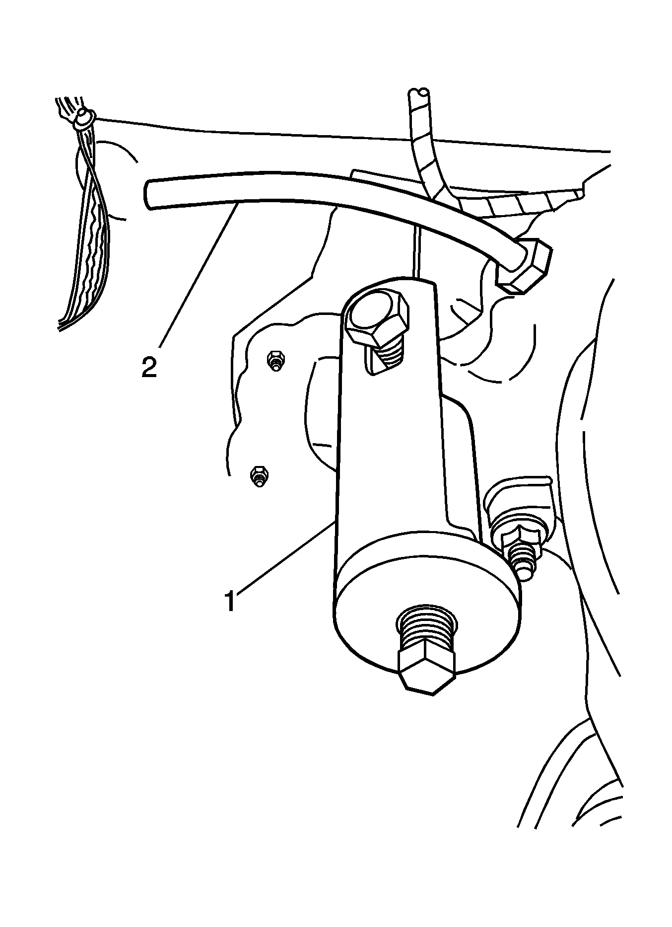
Caution: Incorrect installation of the washer will result in damage to the accumulator end.
Important: Do not exceed 65 N·m(48 lb ft) torque.
Important: A torque wrench must be used to tighten the fixture clamp bolt
Stop tightening of the bolt when either fluid is observed (below the maximum 65 N·m(48 lb ft) torque)
OR
The 65 N·m(48 lb ft) maximum bolt torque is achieved (with no fluid visible in the clear adapter tube).
| 18.1. | If fluid is seen coming out of the inlet port adapter up to 65 N·m (48 lb ft) maximum torque, the hydro-boost booster assembly is "OK". Proceed to Step 19. |
| 18.2. | If NO fluid is seen exiting from the inlet port adapter, complete Steps 19-27, and then repeat Steps 1-18. |
| 18.3. | If no fluid is visible from the second evaluation, replace the hydro-boost unit. Proceed to the appropriate procedure found in this bulletin. |
Tighten
Tighten to 28 N·m(21 lb ft).
| 22.1. | Connect the reservoir outlet hose to the booster unit. Keeping the hose end higher than reservoir, reposition the reservoir onto the mounting studs. |
| 22.2. | Install the remote power steering reservoir mounting nuts. |
Tighten
Tighten to 7 N·m (58 lb in).
Hydro-Boost® Replacement - Avalanche, Express, Savana, Silverado, Sierra, Suburban, Yukon XL, H2
Tools Required
| • | J 35555 Metal Mityvac |
| • | J 43485 Power Steering Bleeder Adapter |
Removal
- Apply the park brake and block the wheels.
- Remove the master cylinder from the booster. Do not remove the pipes from the master cylinder. Set the master cylinder aside in the engine compartment.
- Disconnect the power brake booster inlet hose, the steering gear inlet hose, and the power brake booster outlet hose from the booster assembly.
- Disconnect the electrical connector from the stop lamp switch.
- Remove the retainer from the brake pedal pin.
- Remove the stop lamp switch and the pushrod to the power brake booster from the brake pedal pin.
- Unsnap the stop lamp switch from the power brake booster pushrod.
- Remove the 4 booster to bulkhead nuts.
- Remove the booster assembly.
- Remove the gasket.
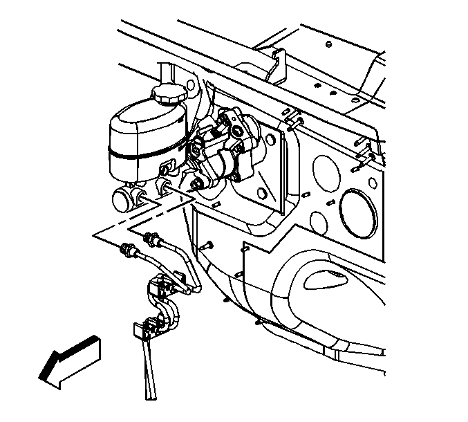
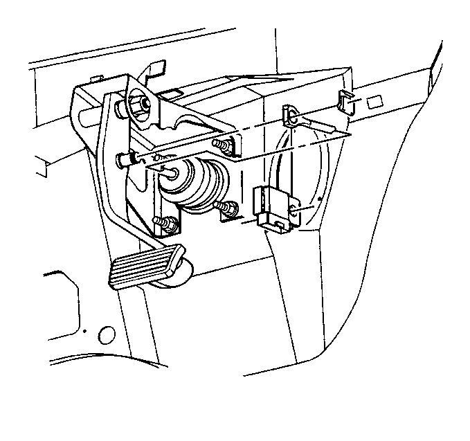
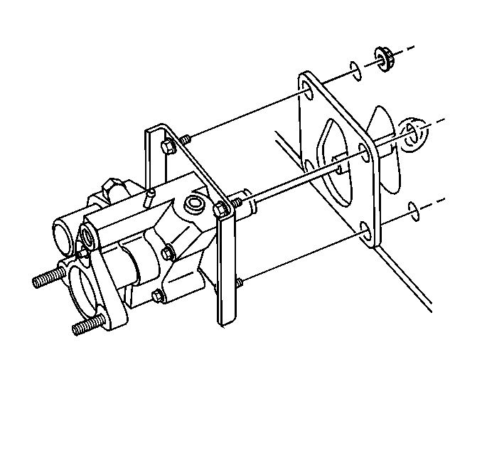
Installation
- Install the gasket.
- Install the booster assembly.
- Install the 4 booster to bulkhead nuts.
- Snap the stop lamp switch onto the pushrod to the power brake booster.
- Install the stop lamp switch with the pushrod on the brake pedal pin.
- Install the brake switch retainer.
- Connect the electrical connector to the stop lamp switch.
- Install the master cylinder to the booster.
- Install the master cylinder mounting nuts.
- Connect the power brake booster outlet hose, the steering gear inlet hose, and the power brake booster inlet hose.
- Remove the pump reservoir cap.
- Fill the pump reservoir with fluid to the FULL COLD level.
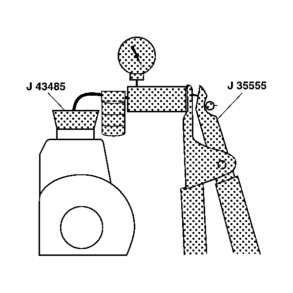
- Attach J 43485, Power Steering Bleeder Adapter, to J 35555, Metal Mityvac, or equivalent.
- Place J 43485 on or in the pump reservoir filler neck.
- Apply a vacuum of 68 kPa (20 in Hg) maximum.
- Wait 1 minute.
- Remove J43485 and J 35555.
- Reinstall the pump reservoir cap.
- Start the engine. Allow the engine to idle.
- Turn the steering wheel 180-360 degrees in both directions 5 times.
- Switch the ignition off.
- Verify the fluid level.
- Release the park brake and unblock the wheels.

Tighten
Tighten the nuts to 36 N·m(26 lb ft).

Tighten
Tighten the nuts to 36 N·m(27 lb ft).
Tighten
| • | Tighten the power brake booster inlet hose to 28 N·m(20 lb ft). |
| • | Tighten the steering gear inlet hose to 28 N·m(20 lb ft). |
Important: Maintain the fluid level throughout the bleed procedure.
Important: Use clean, new power steering fluid only.
Hydro-Boost® Replacement -- Kodiak, TopKick
Tools Required
| • | J 35555 Metal Mityvac |
| • | J 43485 Power Steering Bleeder Adapter |
Removal
- Block the wheels.
- Disconnect the electrical connectors from the electrohydraulic pump and the flow switch.
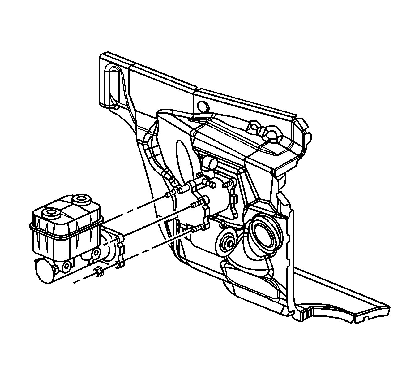
- Remove the master cylinder nuts. Do not remove the pipes from the master cylinder. Position the master cylinder away from the booster head. Secure the master cylinder in an upright position.
- Disconnect the power brake booster inlet hose, the steering gear inlet hose, and the power brake booster outlet hose from the booster assembly.
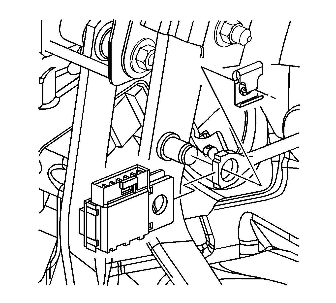
- Remove the booster pump rod retainer from the lever.
- Remove the stop lamp switch from the lever.
- Remove the booster pump rod from the lever.
- Remove the nuts at the booster.
- Remove the booster assembly.
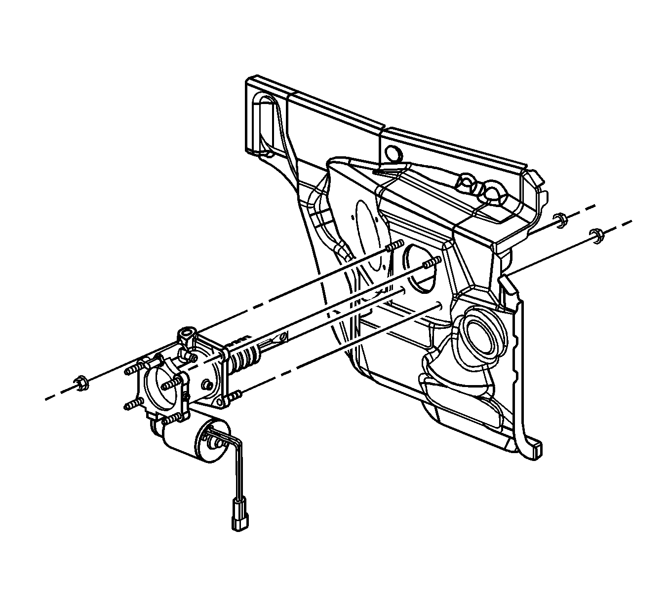
Installation
- Install the booster assembly to the vehicle.
- Install the nuts at the booster.
- Install the booster pump rod to the lever.
- Install the stop lamp switch to the lever.
- Install the booster pump rod retainer.
- Connect the power brake booster outlet hose, the steering gear inlet hose, and the power brake booster inlet hose.
- Install the master cylinder.
- Install the mounting nuts.
- Install the electrical connectors to the electrohydraulic pump and the flow switch.
- Fill the hydraulic pump reservoir.
- Remove the pump reservoir cap.
- Fill the pump reservoir with fluid to the FULL COLD level.
- Attach J43485, Power Steering Bleeder Adapter, to J35555, Metal Mityvac, or equivalent.
- Place J 43485 on or in the pump reservoir filler neck.
- Apply a vacuum of 68 kPa (20 in Hg) maximum.
- Wait 1 minute.
- Remove J43485 and J 35555.
- Reinstall the pump reservoir cap.
- Start the engine. Allow the engine to idle.
- Turn the steering wheel 180-360 degrees in both directions 5 times.
- Switch the ignition off.
- Verify the fluid level.
- Release the park brake and unblock the wheels.

Tighten
Tighten the nuts to 50 N·m(37 lb ft).

Tighten
| • | Tighten the power brake booster inlet hose to 28 N·m(20 lb ft). |
| • | Tighten the steering gear inlet hose to 28 N·m(20 lb ft). |

Tighten
Tighten the mounting bolts to 50 N·m (37 lb
ft).
Important: Maintain the fluid level throughout the bleed procedure.
Important: Use clean, new power steering fluid only.

Courtesy Transportation
The General Motors Courtesy Transportation program is intended to minimize customer inconvenience when a vehicle requires a repair that is covered by the New Vehicle Limited Warranty. The availability of courtesy transportation to customers whose vehicles are within the warranty coverage period and involved in a product recall is very important in maintaining customer satisfaction. Dealers are to ensure that these customers understand that shuttle service or some other form of courtesy transportation is available and will be provided at no charge. Dealers should refer to the General Motors Service Policies and Procedures Manual for Courtesy Transportation guidelines.
Claim Information
Submit a Product Recall Claim with the information indicated below:
Repair Performed | Part Count | Part No. | Parts Allow | CC-FC | Labor Op | Labor Hours | Net Item |
|---|---|---|---|---|---|---|---|
Inspect Hydro-Boost® -- No Further Action Required | N/A | N/A | N/A | MA-96 | V1308 |
| ** |
Avalanche, Silverado, Sierra, Suburban, Yukon XL, H2, Kodiak, TopKick | 0.3 | ||||||
Express, Savana | 0.4 | ||||||
Add: Repeat Inspection | 0.2 | ||||||
Inspect & Replace Hydro-Boost® | 1 | -- | * | MA-96 | V1309 |
| *** |
Avalanche, Silverado, Sierra, Suburban, Yukon XL, H2 | 1.3 | ||||||
Express, Savana | 1.4 | ||||||
Kodiak, TopKick | 1.5 | ||||||
Courtesy Transportation | N/A | N/A | N/A | MA-96 | **** | N/A | ***** |
* The "Parts Allowance" should be the sum total of the current GMSPO Dealer net price plus applicable Mark-Up or Landed Cost Mark-Up (for Export) for the hydraulic brake booster needed to complete the repair. ** The amount identified in the "Net Item" column should represent the sum total of the current GMSPO Dealer net price plus applicable Mark-Up or Landed Cost Mark-Up (for Export) for the power steering fluid needed to perform the required repairs, if needed, not to exceed 118 ml (4 oz). *** The amount identified in the "Net Item" column should represent the sum total of the current GMSPO Dealer net price plus applicable Mark-Up or Landed Cost Mark-Up (for Export) for power steering fluid needed to perform the required repairs, not to exceed 355 ml (12 oz). **** Submit courtesy transportation using normal labor operations for courtesy transportation as indicated in the GM Service Policies and Procedures Manual. ***** The amount identified in the "Net Item" column should represent the actual dollar amount for courtesy transportation. | |||||||
Refer to the General Motors WINS Claims Processing Manual for details on Product Recall Claim Submission.
Customer Notification -- For US and Canada
General Motors will notify customers of this recall on their vehicle (see copy of customer letter included with this bulletin).
Customer Notification -- For IPC
Letters will be sent to known owners of record located within areas covered by the US National Traffic and Motor Vehicle Safety Act. For owners outside these areas, dealers should notify customers using the attached sample letter.
Dealer Recall Responsibility -- For US and Export (US States, Territories, and Possessions)
The US National Traffic and Motor Vehicle Safety Act provides that each vehicle which is subject to a recall of this type must be adequately repaired within a reasonable time after the customer has tendered it for repair. A failure to repair within sixty days after tender of a vehicle is prima facie evidence of failure to repair within a reasonable time. If the condition is not adequately repaired within a reasonable time, the customer may be entitled to an identical or reasonably equivalent vehicle at no charge or to a refund of the purchase price less a reasonable allowance for depreciation. To avoid having to provide these burdensome remedies, every effort must be made to promptly schedule an appointment with each customer and to repair their vehicle as soon as possible. In the recall notification letters, customers are told how to contact the US National Highway Traffic Safety Administration if the recall is not completed within a reasonable time.
Dealer Recall Responsibility -- All
All unsold new vehicles in dealers' possession and subject to this recall MUST be held and inspected/repaired per the service procedure of this recall bulletin BEFORE customers take possession of these vehicles.
Dealers are to service all vehicles subject to this recall at no charge to customers, regardless of mileage, age of vehicle, or ownership, from this time forward.
Customers who have recently purchased vehicles sold from your vehicle inventory, and for which there is no customer information indicated on the dealer listing, are to be contacted by the dealer. Arrangements are to be made to make the required correction according to the instructions contained in this bulletin. A copy of the customer letter is provided in this bulletin for your use in contacting customers. Recall follow-up cards should not be used for this purpose, since the customer may not as yet have received the notification letter.
In summary, whenever a vehicle subject to this recall enters your vehicle inventory, or is in your dealership for service in the future, please take the steps necessary to be sure the recall correction has been made before selling or releasing the vehicle.
March 2005Dear General Motors Customer:
This notice is sent to you in accordance with the requirements of the National Traffic and Motor Vehicle Safety Act. Federal regulation requires that any vehicle lessor receiving this recall notice must forward a copy of this notice to the lessee within ten days.
Reason For This Recall
General Motors has decided that a defect which relates to motor vehicle safety exists in certain 2004 model year Chevrolet Kodiak and GMC TopKick, 2004-2005 model year Chevrolet Avalanche, Express, Silverado, Suburban; GMC Savana, Sierra, Yukon XL; and HUMMER H2 vehicles. On some of these vehicles, the hydraulic brake booster’s pressure accumulator may crack and/or separate from the Hydro-Boost® assembly during normal vehicle operating conditions. If a separation were to occur and the hood of the vehicle were open, fragments from the accumulator could cause injury to people in the immediate area. In addition, the presence of this crack or fractured surface could allow the hydraulic fluid to leak from the accumulator circuit of the booster assembly. The loss of fluid would cause increased steering and braking effort.
What Will Be Done
Your GM dealer will inspect the hydraulic brake booster, and replace it if necessary. This service will be performed for you at no charge .
How Long Will The Repair Take?
This inspection will take approximately 20-40 minutes. If the hydraulic brake booster requires replacement, an additional 1 hour will be required. However, due to service scheduling requirements, your dealer may need your vehicle for a longer period of time.
Contacting Your Dealer
To limit any possible inconvenience, we recommend that you contact your dealer as soon as possible to schedule an appointment for this repair. By scheduling an appointment, your dealer can ensure that the necessary parts will be available on your scheduled appointment date. Should your dealer be unable to schedule a service date within a reasonable time, you should contact the appropriate Customer Assistance Center at the listed number below. The Customer Assistance Center’s hours of operation are from 8:00 AM to 11:00 PM, EST, Monday through Friday.
Division | Number | Text Telephones (TTY) |
|---|---|---|
Chevrolet | 1-800-630-2438 | 1-800-833-2622 |
GMC | 1-866-996-9463 | 1-800-462-8583 |
HUMMER | 1-866-964-8663 |
|
Puerto Rico - English | 1-800-496-9992 |
|
Puerto Rico - Español | 1-800-496-9993 |
|
Virgin Islands | 1-800-496-9994 |
|
Guam | 1-671-648-8650 |
|
If, after contacting the appropriate customer assistance center, you are still not satisfied that we have done our best to remedy this condition without charge and within a reasonable time, you may wish to write the Administrator, National Highway Traffic Safety Administration, 400 Seventh Street SW, Washington, DC 20590 or call 1-888-327-4236.
Customer Reply Form
The enclosed customer reply form identifies your vehicle. Presentation of this form to your dealer will assist in making the necessary correction in the shortest possible time. If you no longer own this vehicle, please let us know by completing the form and mailing it back to us.
Courtesy Transportation
If your vehicle is within the New Vehicle Limited Warranty your dealer may provide you with shuttle service or some other form of courtesy transportation while your vehicle is at the dealership for this repair. Please refer to your Owner’s Manual and your dealer for details on Courtesy Transportation.
Owner Center Online
This free online service offers vehicle and ownership related information and tools tailored to your specific vehicle. To get the most personalized information for your vehicle, visit www.mygmlink.com , and enter your vehicle's 17-character vehicle identification number (VIN) shown on the enclosed customer reply form.
Federal regulation requires that any vehicle lessor receiving this recall notice must forward a copy of this notice to the lessee within ten days.
We are sorry to cause you this inconvenience; however, we have taken this action in the interest of your safety and continued satisfaction with our products.
General Motors Corporation
Enclosure
05006
