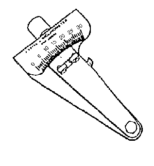
Tools Required
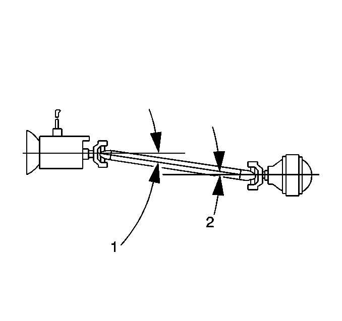
The working angle of a U-joint is formed by the difference between the angles
of two shafts that intersect. One-piece propeller shaft systems have two working angles;
front (1) and rear (2).
| • | The front working angle (1) is formed by the intersection of the
transmission output shaft and the propeller shaft. |
| • | The rear working angle (2) is formed by the intersection of the
propeller shaft and the drive axle pinion. |
Two-piece systems contain three working angles.
When measuring and evaluating driveline working angles, observe the following:
| • | The two working, or cancelling angles should be equal to each other within
1/2 degree to provide effective cancellation of the U-joints. |
| • | Two-piece systems contain an odd, or non-cancelled angle - the front
angle - that should be between 1/10 and 1/2 degree. |
| • | No working angle should exceed 4 degrees. |
| • | No working angle should be equal to zero. An angle of 0 degrees
will cause premature U-joint wear due to a lack of rotation of the needle bearings
in the U-joint. |
| • | Always orientate the J 23498-A
so that it faces the same side of the vehicle for each measurement taken. |
| • | Be sure to accurately record the measurements
taken on a diagram, similar to the one shown. |
Measurement Procedure
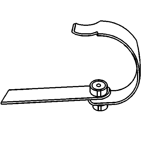
Important: If it is necessary to use the J 23498-20
adapter, first verify the accuracy of the J 23498-20
by inspecting the angle of an accessible
joint using the J 23498-A
, then
inspecting the same joint angle using the J 23498-20
.
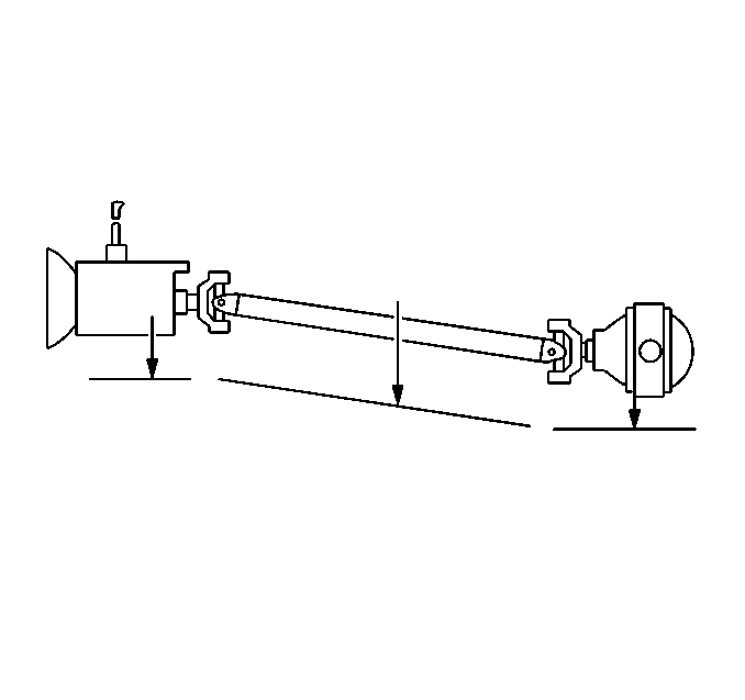
- Raise and support the vehicle. Ensure that the drive axle is supported
at ride height - vehicle body supported by suspension components - with
the wheels free to rotate. Refer to
Lifting and Jacking the Vehicle
in General Information.
- For two-piece propeller shaft systems, inspect the lateral alignment
of the propeller shafts before proceeding.
| 2.1. | From underneath the propeller shafts, look down the length of the shafts
from front to rear. Inspect the alignment of the shafts to each other. |
| 2.2. | From underneath the shafts, if the propeller shafts are not aligned to
each other in a straight line, then the lateral alignment of the propeller shafts
needs to be adjusted before proceeding. |
The propeller shaft support bearing assembly can be relocated slightly to one
side in order to improve the alignment of the shafts. Ensure that you do not create
a ground-out condition against the exhaust or any other component.
- Place the transmission in NEUTRAL.
- Ensure that the vehicle has a full tank of fuel or the equivalent amount
of weight in the rear to simulate a full tank. The weight of 3.8 L (1 gal)
of gasoline is approximately 2.8 kg (6.2 lb).
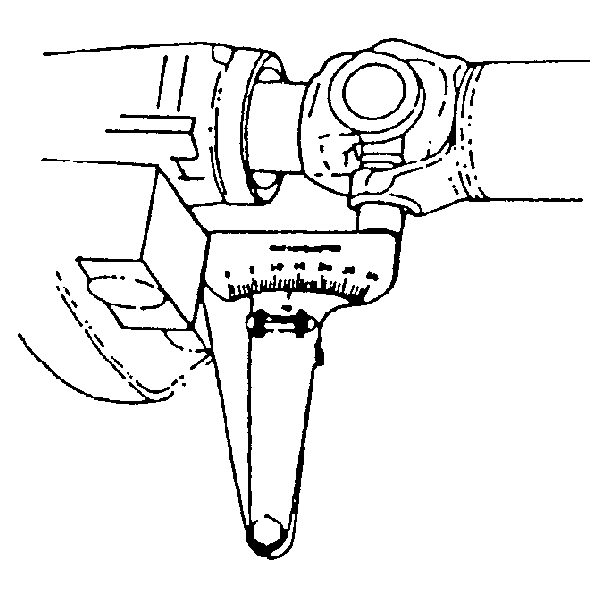
- Clean any corrosion or foreign material from the U-joint bearing caps.
- Remove any of the U-joint bearing cap snap rings that may interfere with
the correct placement of the J 23498-A
.
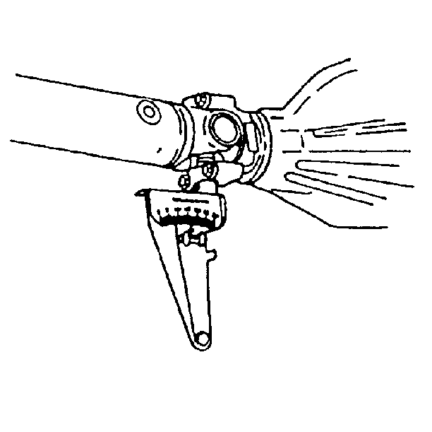
- Measure the angle of the drive axle pinion.
| 7.1. | Rotate the drive axle pinion to align the pinion yoke flanges vertically. |
| 7.2. | Install the J 23498-A
to the lower U-joint bearing cap of the drive axle pinion. |
| 7.3. | Using the J 23498-A
,
measure and record the angle of the drive axle pinion. |
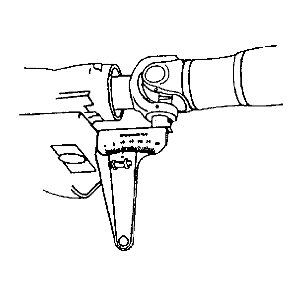
- For one-piece systems, measure the angle
of the transmission output shaft yoke.
| 8.1. | Do not rotate the propeller shaft. With the propeller shaft in the same
position, the transmission output shaft yoke flange will be aligned vertically. |
| 8.2. | Install the J 23498-A
to the lower U-joint bearing cap of the transmission output shaft yoke. |
| 8.3. | Using the J 23498-A
,
measure and record the angle of the transmission output shaft yoke - one-piece
system. |
- For two-piece systems, measure the angle
of the front propeller shaft.
| 9.1. | Do not rotate the propeller shafts. With the propeller shafts in the
same position, the U-joints of the front propeller shaft will be aligned vertically. |
| 9.2. | Install the J 23498-A
to the lower U-joint bearing cap of either of the U-joints on the front propeller
shaft. |
| 9.3. | Using the J 23498-A
,
measure and record the angle of the front propeller shaft - two-piece system. |
- Rotate the propeller shaft, or shafts 1/4 turn.
- For one-piece systems, measure the angle of the front propeller shaft.
| 11.1. | Do not rotate the propeller shaft. With the propeller shaft in this position,
the U-joints of the front propeller shaft will be aligned vertically. |
| 11.2. | Install the J 23498-A
to the lower U-joint bearing cap of either of the U-joints on the front propeller
shaft. |
| 11.3. | Using the J 23498-A
,
measure and record the angle of the front propeller shaft - one-piece system. |
- For two-piece systems, measure the angle
of the transmission output shaft yoke.
| 12.1. | Do not rotate the propeller shafts. With the propeller shafts in this
position, the transmission output shaft yoke flanges will be aligned vertically. |
| 12.2. | Install the J 23498-A
to the lower U-joint bearing cap of the transmission output shaft yoke. |
| 12.3. | Using the J 23498-A
,
measure and record the angle of the transmission output shaft yoke - two-piece
system. |
- Remove the J 23498-A
.
- Install any U-joint bearing cap snap rings that were removed prior to
installing the J 23498-A
.
- Calculate the working angles at each intersection of two shafts.
Subtract the larger number from the smaller to obtain the working angle. For
example: If the drive axle pinion has an angle of 16 degrees and the connecting
propeller shaft has an angle of 13 degrees, then the working angle of that
intersection is 3 degrees.
- Compare the working angles of cancelling U-joints, beginning at the rear-most
position.
- If the working angles of two cancelling U-joints are not within 1/2 degree
of each other, or if one or both of the angles exceed 4 degrees, then the angle
requires adjustment.
- For two-piece systems, if the working angle of the non-cancelling, front
U-joint is not between 1/10-1/2 degree, then the angle requires adjustment.
